Table of Contents
Advertisement
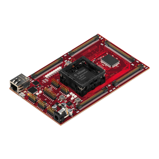
TriBoard TC3X9
TriBoard Manual TC3X9
Hardware: TriBoard TC3X9 TH V2.0( 1) and TriBoard TC3X9 V2.0
About this document
Scope and purpose
The User Manual provide information about using, configuration and connecting the TriBoard with Infineon
AURIX™ TC3X9 device. The manual provide information for different hardware types. There exist different
hardware with Through Hole socket (TriBoard TC3X9 TH) and soldered devices (TriBoard TC3X9). The schematic
is identically for the all boards if not other mentioned in chapter schematic. The placing on the boards is
identically, all components are on the same location. Only the routing is different (socket need more space and
has through hole). All figures are valid for each board if not differently mentioned.
Intended audience
Design, verfication, test and software engineers will use this document to get an understanding of the
functionality and connections of the TriBoard.
User Manual
www.infineon.com
Please read the Important Notice and Warnings at the end of this document
TriBoard TC3X9 TH V2.0(1) and TriBoard TC3X9 V2.0
V2.1
2017-11
Advertisement
Table of Contents

Related Manuals for Infineon TriBoard TC3X9 TH


Summary of Contents for Infineon TriBoard TC3X9 TH
- Page 1 AURIX™ TC3X9 device. The manual provide information for different hardware types. There exist different hardware with Through Hole socket (TriBoard TC3X9 TH) and soldered devices (TriBoard TC3X9). The schematic is identically for the all boards if not other mentioned in chapter schematic. The placing on the boards is identically, all components are on the same location.
-
Page 2: Table Of Contents
TriBoard Manual TC3X9 Hardware: TriBoard TC3X9 TH V2.0(1) and TriBoard TC3X9 V2.0 Table of Contents Table of Contents About this document ..............Preface-1 Table of Contents . -
Page 3: Table Of Contents
Known problems (TriBoard TC3X9 TH V2.0(1)) ........ -
Page 4: Introduction
TriBoard Manual TC3X9 Hardware: TriBoard TC3X9 TH V2.0(1) and TriBoard TC3X9 V2.0 Introduction Introduction We congratulate you on your purchase of the TriCore Evaluation Board. This kit is a versatile tool, providing quick access to the capabilities of TriCore's powerful architecture. -
Page 5: Features
Features Features Summary of Features – Infineon’s TC3X9 (TC399, TC389) AURIX™ 2G Controller in LFBGA-516 Package – Infineon’s TC3X7 (TC397, TC387) AURIX™ 2G Controller in LFBGA-292 Package – Burst Flash up to 4MBytes (only with TC399) – asynchronous SRAM up to 2MByte (only with TC399) –... - Page 6 TriBoard Manual TC3X9 Hardware: TriBoard TC3X9 TH V2.0(1) and TriBoard TC3X9 V2.0 Features – Infineon’s LIN-Transceiver TLE 7259-3GE – USB to UART bridge FT2232HL (FTDI) – Integrated 10/100/1000M Ethernet Precision Transceiver RTL8211FI-CG (Realtek) – 8 general purpose LEDs – 2K I2C Serial Eeprom with EUI-48™...
-
Page 7: Block Diagram
TriBoard Manual TC3X9 Hardware: TriBoard TC3X9 TH V2.0(1) and TriBoard TC3X9 V2.0 Features Block Diagram XTAL RJ45 CAN0 TxCAN0 Twisted Pair RGMII RxCAN 0 Transceiver CAN1 TxCAN1 HSCT0 - TX/RX RxCAN1 TC3X9 HSCT1 - TX/RX (e.g. OCDS1 ONLY TC399 Micro... -
Page 8: Placement
TriBoard Manual TC3X9 Hardware: TriBoard TC3X9 TH V2.0(1) and TriBoard TC3X9 V2.0 Features Placement X306 X704 X701 X202 Y301 Y401 S202 D302 D303 D304 D305 D306 D307 D308 D 309 X201 X403 U 401 X404 D401 D402 X402 T301 U604... -
Page 9: Triboard Information
VEBU pins of TC399 are connected to VEXT on TC389. Therefore you can’t use a TC389 in a board assembled for TC399. The soldered boards always will have the correct assembling. For TriBoard TC3X9 TH (socket variante) use with care. -
Page 10: Failsafe Handling
TriBoard Manual TC3X9 Hardware: TriBoard TC3X9 TH V2.0(1) and TriBoard TC3X9 V2.0 TriBoard Information +3,3V via LDO directly from pre regulator (used by Ethernet PHY and on board memories if assembled) Applying a stable supply voltage causes the power on reset after a short period. The three LED's (V_UC, +3.3V, +1V25) indicate the status of the on board generated voltages. -
Page 11: Clock
TriBoard Manual TC3X9 Hardware: TriBoard TC3X9 TH V2.0(1) and TriBoard TC3X9 V2.0 TriBoard Information – D306 up to D309 (blue) -> toogle LEDs connected to P20.11 ... P20.14 – D504 RST (red) -> RESET LED indicate the reset state of the board (/ESR0) –... -
Page 12: Serial Connection To Pc
TriBoard Manual TC3X9 Hardware: TriBoard TC3X9 TH V2.0(1) and TriBoard TC3X9 V2.0 TriBoard Information 3.7.1 Serial Connection to PC After the first connection of USB to a PC the needed driver will be installed automatically. During this there will be created a new COM port on PC. This COM port can be used to communicate with the board via ASCLIN0 of the device. -
Page 13: Flexray™ (E-Ray)
TriBoard Manual TC3X9 Hardware: TriBoard TC3X9 TH V2.0(1) and TriBoard TC3X9 V2.0 TriBoard Information Per default the miniWiggler is connected to the DAP. It is possible to change the connection to DAPE (DAP of emulation device if available). If resistors R214, R215 and R216 assembled (default) then the standard DAP is connected to miniWiggler otherwise if R217, R218 and R219 are assembled the the DAPE of enulation device is connected to miniWiggler. -
Page 14: Ethernet
TriBoard Manual TC3X9 Hardware: TriBoard TC3X9 TH V2.0(1) and TriBoard TC3X9 V2.0 TriBoard Information 3.12 Ethernet The TriBoard provide a RJ45 connector (X306) for twisted pair ethernet connections.The TriBoard use a Realtek Integrated 10/100/1000M Ethernet Precision Transceiver RTL8211FI-CG as physical interface device. For more information about the ethernet modul see TC3X9 User’s Manual, about the PHY see the RTL8211F datasheet. -
Page 15: Adc
TriBoard Manual TC3X9 Hardware: TriBoard TC3X9 TH V2.0(1) and TriBoard TC3X9 V2.0 TriBoard Information C316 C315 C314 C317 X801 X804 R389 C308 C305 CB315 C312 R3110 CB312 C313 C404 CB316 C406 CB314 C405 CB409 R370 R372 R3107 CB313 CB311 R414... -
Page 16: Other Peripherals
TriBoard Manual TC3X9 Hardware: TriBoard TC3X9 TH V2.0(1) and TriBoard TC3X9 V2.0 TriBoard Information C316 C315 C314 C317 X801 X804 R389 C308 C305 CB315 C312 R3110 CB312 C313 C404 CB316 C406 CB314 C405 CB409 R370 R372 R3107 CB313 CB311 R414... -
Page 17: Debug System
TriBoard Manual TC3X9 Hardware: TriBoard TC3X9 TH V2.0(1) and TriBoard TC3X9 V2.0 TriBoard Information 3.18 Debug System 3.18.1 OCDS1 The OCDS1 signals are connected to the IDC16 plug (X401). They work with the port supply of Microcontroller (+5V default or +3,3V). For pinout of the connector see Figure 6-11. - Page 18 TriBoard Manual TC3X9 Hardware: TriBoard TC3X9 TH V2.0(1) and TriBoard TC3X9 V2.0 TriBoard Information X306 X704 X701 C310 X202 L301 S202 R399 CB319 C318 C311 X404 R382 Y401 C309 CB318 R3104 R392 R393 R394 R395 R396 R397 R398 R402 R439...
-
Page 19: Agbt (Optional)
TriBoard Manual TC3X9 Hardware: TriBoard TC3X9 TH V2.0(1) and TriBoard TC3X9 V2.0 TriBoard Information 3.18.6 AGBT (optional) The TriBoard provide a 22 pin high speed samtec connector (X405) for highest speed connection via AGBT. This connector should be assembled by your self if needed. - Page 20 TriBoard Manual TC3X9 Hardware: TriBoard TC3X9 TH V2.0(1) and TriBoard TC3X9 V2.0 TriBoard Information C316 C315 C314 C317 X801 X804 R389 C308 C305 CB315 C312 R3110 CB312 C313 C404 CB316 C406 CB314 C405 CB409 R370 R372 R3107 CB313 CB311 R414...
-
Page 21: Triboard Configuration
TriBoard Manual TC3X9 Hardware: TriBoard TC3X9 TH V2.0(1) and TriBoard TC3X9 V2.0 TriBoard Configuration TriBoard Configuration HW Boot Configuration Figure 4-1 HW Configuration DIP-Switches The picture above shows the definition of the boot HW configuration switch. The meaning of the switches will be... -
Page 22: Assembly Options
TriBoard Manual TC3X9 Hardware: TriBoard TC3X9 TH V2.0(1) and TriBoard TC3X9 V2.0 TriBoard Configuration Assembly Options 4.2.1 General optional resistors Table 4-2 General optional resistors (default assembly in brackets) Component Description R202 Connect P20.2 (/TESTMODE) to GND (not assembled) R203... - Page 23 TriBoard Manual TC3X9 Hardware: TriBoard TC3X9 TH V2.0(1) and TriBoard TC3X9 V2.0 TriBoard Configuration X306 X704 X701 C310 X202 L301 S202 R399 CB319 C318 C311 X404 R382 Y401 C309 CB318 R398 R3104 R392 R393 R394 R395 R396 R397 R402 R439...
-
Page 24: Resistors For Peripherals
TriBoard Manual TC3X9 Hardware: TriBoard TC3X9 TH V2.0(1) and TriBoard TC3X9 V2.0 TriBoard Configuration 4.2.2 Resistors for peripherals Table 4-3 Resistors for peripherals (default assembly in brackets) Component Description R220 Connect V_VR with VDDM (assembled) R221 Connect +3V3 with VDDM (not assembled) - Page 25 TriBoard Manual TC3X9 Hardware: TriBoard TC3X9 TH V2.0(1) and TriBoard TC3X9 V2.0 TriBoard Configuration Table 4-3 Resistors for peripherals (default assembly in brackets) (continued) Component Description R373 Connect P11.4 with TXC of Ethernet PHY (assembled) R374 Connect P11.6 with TXCTL of Ethernet PHY (assembled) R375 Connect P12.1 with MDIO of Ethernet PHY (assembled)
-
Page 26: Resistors For Memories
TriBoard Manual TC3X9 Hardware: TriBoard TC3X9 TH V2.0(1) and TriBoard TC3X9 V2.0 TriBoard Configuration C316 C315 C314 C317 X801 X804 R389 C308 C305 CB315 C312 R3110 CB312 C313 C404 CB316 C406 CB314 C405 CB409 R370 R372 R3107 CB313 CB311 R414... - Page 27 TriBoard Manual TC3X9 Hardware: TriBoard TC3X9 TH V2.0(1) and TriBoard TC3X9 V2.0 TriBoard Configuration X306 X704 X701 C310 X202 L301 S202 R399 CB319 C318 C311 X404 R382 Y401 C309 CB318 R398 R3104 R392 R393 R394 R395 R396 R397 R402 R439...
-
Page 28: Signal (On Board Used) Description
TriBoard Manual TC3X9 Hardware: TriBoard TC3X9 TH V2.0(1) and TriBoard TC3X9 V2.0 Signal (on board used) Description Signal (on board used) Description For more information about the signals please see the user manual/datasheet for TC3X9 and/or the schematics of the board. -
Page 29: Config Signals
TriBoard Manual TC3X9 Hardware: TriBoard TC3X9 TH V2.0(1) and TriBoard TC3X9 V2.0 Signal (on board used) Description Config Signals Table 5-3 Config Signals Short name Description P14.5 HWCFG1 (EVR33OFF / EVR33ON) P14.2 HWCFG2 (EVRCOFF / EVRCON) P14.4 HWCFG6 (Pins in tristate / Pins with pull-up) P14.3... -
Page 30: Peripheral Signals
TriBoard Manual TC3X9 Hardware: TriBoard TC3X9 TH V2.0(1) and TriBoard TC3X9 V2.0 Signal (on board used) Description Peripheral Signals Table 5-6 Peripheral Signals Short name Description P14.1 ASCLIN0 Receive Input A CAN01 Receive Input B (optional) P14.0 ASCLIN0 Transmit Output CAN01 Transmit Output (optional) P15.3... -
Page 31: Ebu Signals
TriBoard Manual TC3X9 Hardware: TriBoard TC3X9 TH V2.0(1) and TriBoard TC3X9 V2.0 Signal (on board used) Description Table 5-6 Peripheral Signals (continued) Short name Description REFCLK Ethernet GREFCLK Input (P11.5) TCTL Ethernet TCTL Output (P11.6) RXD3 Ethernet RXD3 Input A (P11.7) RXD2 Ethernet RXD2 Input A (P11.8) - Page 32 TriBoard Manual TC3X9 Hardware: TriBoard TC3X9 TH V2.0(1) and TriBoard TC3X9 V2.0 Signal (on board used) Description Table 5-7 EBU Signals (continued) Short name Description AD3 / P30.8 Address Data Line 3 Input/Output AD4 / P30.6 Address Data Line 4 Input/Output AD5 / P30.10...
- Page 33 TriBoard Manual TC3X9 Hardware: TriBoard TC3X9 TH V2.0(1) and TriBoard TC3X9 V2.0 Signal (on board used) Description Table 5-7 EBU Signals (continued) Short name Description A9 / P24.4 Address Line 9 Output A10 / P24.8 Address Line 10 Output A11 / P24.0 Address Line 11 Output A12 / P24.5...
-
Page 34: Connector Pin Assignment
TriBoard Manual TC3X9 Hardware: TriBoard TC3X9 TH V2.0(1) and TriBoard TC3X9 V2.0 Connector Pin Assignment Connector Pin Assignment The TriBoard will be shipped with five male (plug) connectors on top layer and five female (socket) connectors on bottom layer. The default connectors are 80-pol. Board to Board connectors from Samtec: http://www.samtec.com... -
Page 35: Tc3X9 Connector / Top View
TriBoard Manual TC3X9 Hardware: TriBoard TC3X9 TH V2.0(1) and TriBoard TC3X9 V2.0 Connector Pin Assignment TC3X9 Connector / Top View BUS EXPANSION (X701,X801) PERIPHERALS (X702,X802) P30.9 P21.6 VCC_IN VCC_IN P30.14 P21.7 VCC_IN VCC_IN P30.13 9 10 P24.14 P22.4 9 10 P22.8... - Page 36 TriBoard Manual TC3X9 Hardware: TriBoard TC3X9 TH V2.0(1) and TriBoard TC3X9 V2.0 Connector Pin Assignment ADC (X703, X803) GTM / PORTS (X704,X804) AN16 P00.9 P11.14 AN17 P00.10 P11.15 AN18 P02.0 P14.11 9 10 9 10 11 12 AN19 P02.1 P14.12...
- Page 37 TriBoard Manual TC3X9 Hardware: TriBoard TC3X9 TH V2.0(1) and TriBoard TC3X9 V2.0 Connector Pin Assignment A DC2 (X705, X 805) AN48 AN64 AN49 AN65 AN50 9 10 AN66 11 12 AN51 AN67 AN52 13 14 AN68 15 16 AN53 AN69...
-
Page 38: Power Connector Pinout
TriBoard Manual TC3X9 Hardware: TriBoard TC3X9 TH V2.0(1) and TriBoard TC3X9 V2.0 Connector Pin Assignment Power connector pinout +3,5V...40V Figure 6-4 Power connector pinout (Roka 520 2550) USB connector pinout Figure 6-5 USB connector pinout (Micro USB B-type) FlexRay™ (ERAY) connector pinout Figure 6-6 FlexRay™... -
Page 39: Lin Connector Pinout
TriBoard Manual TC3X9 Hardware: TriBoard TC3X9 TH V2.0(1) and TriBoard TC3X9 V2.0 Connector Pin Assignment LIN connector pinout Figure 6-8 LIN connector pinout (IDC10) HSCT connector pinout Figure 6-9 HSCT connector pinout (IEE1394 6-conductor) Ethernet connector pinout Figure 6-10 Ethernet connector pinout (RJ45) User Manual V2.1... -
Page 40: Ocds1 Connector Pinout
TriBoard Manual TC3X9 Hardware: TriBoard TC3X9 TH V2.0(1) and TriBoard TC3X9 V2.0 Connector Pin Assignment 6.10 OCDS1 connector pinout Figure 6-11 OCDS1 connector pinout (IDC16) 6.11 DAP connector pinout Figure 6-12 DAP connector pinout (Samtec FTSH10) User Manual V2.1 TriBoard TC3X9 TH V2.0(1) and TriBoard TC3X9 V2.0... -
Page 41: Etk Connector Pinout
TriBoard Manual TC3X9 Hardware: TriBoard TC3X9 TH V2.0(1) and TriBoard TC3X9 V2.0 Connector Pin Assignment 6.12 ETK connector pinout Figure 6-13 ETK connector pinout (Samtec TFM-105) 6.13 Ethernet miniWiggler power connector pinout Figure 6-14 Ethernet miniWiggler connector pinout (JST B4B-PH) User Manual V2.1... -
Page 42: Agbt Connector Pinout
TriBoard Manual TC3X9 Hardware: TriBoard TC3X9 TH V2.0(1) and TriBoard TC3X9 V2.0 Connector Pin Assignment 6.14 AGBT connector pinout 1 0 1 2 1 4 1 6 1 8 2 0 2 2 G N D G N D 1 1 1 3 1 5... -
Page 43: Schematic And Layout
TriBoard Manual TC3X9 Hardware: TriBoard TC3X9 TH V2.0(1) and TriBoard TC3X9 V2.0 Schematic and Layout Schematic and Layout Known problems 7.1.1 Known problems (TriBoard TC3X9 TH V2.0(1)) R386 is assembled via wire wrap on version V2.0. 7.1.2 Known problems (TriBoard TC3X9 V2.0) No problems known. - Page 44 TriBoard Manual TC3X9 Hardware: TriBoard TC3X9 TH V2.0(1) and TriBoard TC3X9 V2.0 Schematic and Layout Figure 7-1 Schematic - Project User Manual V2.1 TriBoard TC3X9 TH V2.0(1) and TriBoard TC3X9 V2.0 2017-11...
- Page 45 TriBoard Manual TC3X9 Hardware: TriBoard TC3X9 TH V2.0(1) and TriBoard TC3X9 V2.0 Schematic and Layout Figure 7-2 Schematic - Clock, Config, Debug, Ports and ADC User Manual V2.1 TriBoard TC3X9 TH V2.0(1) and TriBoard TC3X9 V2.0 2017-11...
- Page 46 TriBoard Manual TC3X9 Hardware: TriBoard TC3X9 TH V2.0(1) and TriBoard TC3X9 V2.0 Schematic and Layout Figure 7-3 Schematic - On Board Peripherals User Manual V2.1 TriBoard TC3X9 TH V2.0(1) and TriBoard TC3X9 V2.0 2017-11...
- Page 47 TriBoard Manual TC3X9 Hardware: TriBoard TC3X9 TH V2.0(1) and TriBoard TC3X9 V2.0 Schematic and Layout Figure 7-4 Schematic - miniWiggler JDS and Debug connectors User Manual V2.1 TriBoard TC3X9 TH V2.0(1) and TriBoard TC3X9 V2.0 2017-11...
- Page 48 TriBoard Manual TC3X9 Hardware: TriBoard TC3X9 TH V2.0(1) and TriBoard TC3X9 V2.0 Schematic and Layout Figure 7-5 Schematic - Power Supply User Manual V2.1 TriBoard TC3X9 TH V2.0(1) and TriBoard TC3X9 V2.0 2017-11...
- Page 49 TriBoard Manual TC3X9 Hardware: TriBoard TC3X9 TH V2.0(1) and TriBoard TC3X9 V2.0 Schematic and Layout Figure 7-6 Schematic - On Board SRAM and Flash User Manual V2.1 TriBoard TC3X9 TH V2.0(1) and TriBoard TC3X9 V2.0 2017-11...
- Page 50 TriBoard Manual TC3X9 Hardware: TriBoard TC3X9 TH V2.0(1) and TriBoard TC3X9 V2.0 Schematic and Layout Figure 7-7 Schematic - Connectors (Plug) User Manual V2.1 TriBoard TC3X9 TH V2.0(1) and TriBoard TC3X9 V2.0 2017-11...
- Page 51 TriBoard Manual TC3X9 Hardware: TriBoard TC3X9 TH V2.0(1) and TriBoard TC3X9 V2.0 Schematic and Layout Figure 7-8 Schematic - Connectors (Socket) User Manual V2.1 TriBoard TC3X9 TH V2.0(1) and TriBoard TC3X9 V2.0 2017-11...
-
Page 52: Layout
TriBoard Manual TC3X9 Hardware: TriBoard TC3X9 TH V2.0(1) and TriBoard TC3X9 V2.0 Schematic and Layout Layout Figure 7-9 Component Plot Top Layer User Manual 7-10 V2.1 TriBoard TC3X9 TH V2.0(1) and TriBoard TC3X9 V2.0 2017-11... - Page 53 TriBoard Manual TC3X9 Hardware: TriBoard TC3X9 TH V2.0(1) and TriBoard TC3X9 V2.0 Schematic and Layout Figure 7-10 Component Plot Bottom Layer User Manual 7-11 V2.1 TriBoard TC3X9 TH V2.0(1) and TriBoard TC3X9 V2.0 2017-11...
-
Page 54: Layout With Dimensioning
TriBoard Manual TC3X9 Hardware: TriBoard TC3X9 TH V2.0(1) and TriBoard TC3X9 V2.0 Schematic and Layout Layout with Dimensioning The following dimensions should be used for development of extension boards. Figure 7-11 Dimensioning (mm) User Manual 7-12 V2.1 TriBoard TC3X9 TH V2.0(1) and TriBoard TC3X9 V2.0... - Page 55 TriBoard Manual TC3X9 Hardware: TriBoard TC3X9 TH V2.0(1) and TriBoard TC3X9 V2.0 Schematic and Layout Figure 7-12 Dimensioning (mil) The dimensioning is valid for all TriBoards. User Manual 7-13 V2.1 TriBoard TC3X9 TH V2.0(1) and TriBoard TC3X9 V2.0 2017-11...
- Page 56 TriBoard Manual TC3X9 Hardware: TriBoard TC3X9 TH V2.0(1) and TriBoard TC3X9 V2.0 Revision History Page or Item Subjects (major changes since previous revision) V2.1, 2017-11 Update schematic (R386 added) Correct table 4-2 (switch R526 and R527) User Manual RevisionHistory-1 V2.1 TriBoard TC3X9 TH V2.0(1) and TriBoard TC3X9 V2.0...
- Page 57 Infineon Technologies, Infineon Technologies in customer's applications. Document reference Infineon Technologies’ products may not be used in The data contained in this document is exclusively Doc_Number any applications where a failure of the product or any intended for technically trained staff.
Need help?
Do you have a question about the TriBoard TC3X9 TH and is the answer not in the manual?
Questions and answers