
Related Manuals for HP Engage Go 10


Summary of Contents for HP Engage Go 10
- Page 1 User Guide SUMMARY This guide provides information about components, network connection, power management, security, backing up, and more.
- Page 2 United States and/or other countries. microSD bound by the terms of the HP End User License Not all features are available in all editions is a trademark or registered trademark of Agreement (EULA).
- Page 3 About this guide This guide provides basic information for using and upgrading this product. WARNING! Indicates a hazardous situation that, if not avoided, could result in serious injury or death. CAUTION: Indicates a hazardous situation that, if not avoided, could result in minor or moderate injury. IMPORTANT: Indicates information considered important but not hazard-related (for example, messages related to property damage).
- Page 4 About this guide...
-
Page 5: Table Of Contents
Attaching an optional fingerprint reader to the I/O connectivity base................24 4 Configuring the software ..............................26 Touch screen calibration for Windows 10 Professional and Windows 10 IoT Enterprise for Retail ......26 Configuring optional HP integrated peripheral modules ....................26 Updating the mobile system ............................26 Downloading HP Firmware Installer ........................26 Installing updates ..............................27... - Page 6 The HP commitment ..............................33 International Association of Accessibility Professionals (IAAP) ................34 Finding the best assistive technology ........................34 Assessing your needs ............................34 Accessibility for HP products ...........................34 Standards and legislation..............................35 Standards.................................35 Mandate 376 – EN 301 549..........................35 Web Content Accessibility Guidelines (WCAG) ....................35 Legislation and regulations .............................36...
-
Page 7: Locating Hp Resources
Locating HP resources Read this chapter to learn about where to find additional HP resources. Product information To locate resources that provide product details, how-to information, and more, use this table. Table 1-1 Where to find product information Topic Location Technical specifications To find the QuickSpecs for your product, go to http://www.hp.com/go/quickspecs, and... -
Page 8: Product Documentation
You can find your HP Limited Warranty located with the user guides on your product. The warranty might be on a CD or DVD provided in the box. In some countries or regions, HP might provide a printed warranty in the box. For countries or regions where the warranty is not provided in printed format, you can request a copy from http://www.hp.com/go/... -
Page 9: Product Updates
Topic Location Audible beep and light code definitions See the computer Maintenance and Service Guide at http://www.hp.com/support. Follow the instructions to find your product, and then select Manuals. POST error codes See the computer Maintenance and Service Guide at http://www.hp.com/support. Follow the instructions to find your product, and then select Manuals. -
Page 10: Computer Features
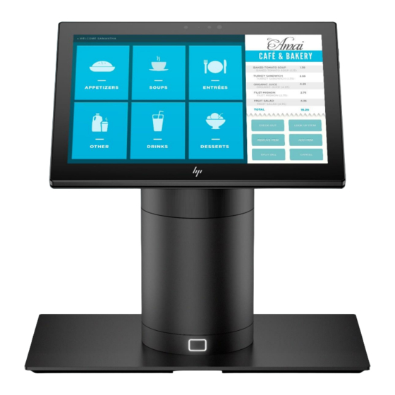
Mobile system with grip Convertible system with grip The HP Engage Go 10 is designed for long-term deployment within general retail, hospitality, and other markets. It includes the following features: Integrated convertible form factor available in convertible system and convertible system with grip ●... - Page 11 25.4 cm (10.0 in) display panel; high definition (1800 × 1200) resolution, 340 nit, multi-touch, Corning ● Gorilla Glass 5 Docking stand ● Major integrated peripherals: ● Barcode scanner with integrated audio/video feedback and trigger button (configurable as upward – facing or downward facing) Optional fingerprint reader –...
-
Page 12: Mobility Head Unit Features
MicroSD card reader – Headset jack – Power connector – Mobility head unit features To identify the mobility head unit features, use this illustration and table. Table 2-1 Identifying the mobility head unit features Features Upward-facing laser barcode scanner* (optional) Fingerprint reader (optional) Power button Barcode scanner button (optional) -
Page 13: Integrated Features
Integrated features To identify the computer features, use this illustration and table. NOTE: The integrated devices shown are optional. Table 2-2 Identifying the integrated features Features 25.4 cm (10.0 in), 1800 × 1200, high definition display Mobile case Docking release button Biometric fingerprint reader (optional) I/O connectivity base Docking stand... -
Page 14: Advanced I/O Connectivity Base Components
Table 2-3 Identifying the basic I/O connectivity base features Features RJ-11 (cash drawer) jack USB Type-C port Power connector RJ-45 (network) jack USB Type-C® powered port Security cable slot Powered serial ports (3) microSD™ card reader (select products only) USB 2.0 ports (4) Headset jack USB SuperSpeed 5 Gbps ports (2) IMPORTANT:... -
Page 15: Multi-Charger Components
Multi-charger components You can charge up to four mobility head units in the multi-charger. To identify charger features, use this illustration and table. NOTE: You can only use the multi-charger with mobile system with grip models and convertible system with grip models. Table 2-5 Identifying the multi-charger features Features... -
Page 16: Locating The Mobile System Power Button
Locating the mobile system power button The computer power button is located on the top-right edge of the bezel. Locating the I/O connectivity base power button The power button is located on the underside of the I/O connectivity base. The head unit controls the I/O connectivity base. When the head unit is turned off, the I/O connectivity base is turned off, and power is not available from the I/O connectivity base ports. -
Page 17: Adjusting The Mobility Head Unit
Adjusting the mobility head unit You can tilt the mobility head unit by as much as 10° when you set the angle between 50° and 60°. You can swivel the mobility head unit 180° in either direction. Mobile system serial number location Each computer has a unique serial number and a product ID number that are located on the exterior of the computer. -
Page 18: Installing A Security Cable On The I/O Connectivity Base
Installing a security cable on the I/O connectivity base You can secure the I/O connectivity base to a fixed object with an optional keyed security cable lock and an optional security cable available from HP. NOTE: The security cable is sold separately as an aftermarket option kit only. -
Page 19: Hardware Setup
It also provides electrical and mechanical safety information. This guide is located on the web at http://www.hp.com/ergo. IMPORTANT: Static electricity can damage the electrical components of the computer or optional equipment. -
Page 20: Attaching The Mobility Head Unit To The Dock
You can use two authentication methods to release the mobility head unit. Set up the authentication methods using the HP SureLock wizard. Windows® user authentication: You can define a group that allows users to release the mobility head unit ●... -
Page 21: Attaching An I/O Connectivity Base To The Mobile System
Press the lock release button (1) on the front of the dock’s column, and then lift the mobility head unit ▲ (2) off the dock. Attaching an I/O connectivity base to the mobile system You can attach an I/O connectivity base to the bottom of the stand. To attach an I/O connectivity base: Turn off the mobility system properly through the operating system, and turn off any external devices. - Page 22 Connect the USB Type-C power cable to the USB Type-C port on the underside of the stand column. Place the I/O connectivity base onto the bottom of the stand (1), and then tighten the four screws on the underside of the I/O connectivity base (2) to secure the I/O connectivity base to the dock. Be sure that the USB Type-C power cable is routed through the gap between the back of the I/O connectivity base and the stand.
-
Page 23: Connecting A Standalone I/O Connectivity Base To The Mobile System
To connect and secure the USB Type-C power cable, attach the cable clip to the cable (1), insert the cable tie into the hole (2) below the USB Type-C port on the I/O connectivity base, and then slide the cable clip onto the cable tie and connect the cable to the port (3). -
Page 24: Configuring The I/O Connectivity Base Powered Serial Ports
Connect the AC adapter to the I/O connectivity base and a grounded AC outlet. See Connecting an AC adapter to power on page Configuring the I/O connectivity base powered serial ports You can configure the serial ports as standard (unpowered) serial ports or powered serial ports. Some devices use a powered serial port. -
Page 25: Attaching The Standard Case To The Mobility Head Unit
Adjust the voltage select switch behind each serial port to the setting that you want. Place the bottom plate onto the I/O connectivity base (1), and then secure the plate to the I/O connectivity base with the five screws (2). Reconnect the I/O connectivity base power cord and peripheral devices. -
Page 26: Attaching The Rugged Case To The Mobility Head Unit
Slide the payment bump side of the mobility head unit into the case (1), rotate the unit down into the case (2), and then securely snap the lip of the case around the unit (3). If your mobility head unit includes a fingerprint reader, remove the fingerprint reader insert from the case. -
Page 27: Mounting The Mobile System To A Countertop
Mounting the mobile system to a countertop You can use an optional countertop mounting bracket to mount the computer head unit and column to a countertop. NOTE: The mounting bracket requires an 80 mm (3 in) hole in the countertop. The thickness of the countertop must be 10 mm (0.4 in) to 50 mm (2 in). - Page 28 Hold the top piece of the mounting bracket against the bottom of the column, route the cables through the hole in the mounting surface, and then place the column over the hole on the mounting surface. The bottom piece of the mounting bracket can be oriented in two ways, depending on the thickness of your mounting surface.
-
Page 29: Connecting A Standalone Optional Fingerprint Reader To The I/O Connectivity Base
Connecting a standalone optional fingerprint reader to the I/O connectivity base You can use the optional fingerprint reader as a standalone device, or you can attach it to the I/O connectivity base. To connect a standalone optional fingerprint reader to the I/O connectivity base: Turn off the mobility system properly through the operating system, and turn off any external devices. -
Page 30: Attaching An Optional Fingerprint Reader To The I/O Connectivity Base
Attaching an optional fingerprint reader to the I/O connectivity base You can use the optional fingerprint reader as a standalone device, or you can attach it to the I/O connectivity base. To connect an optional fingerprint reader to the I/O connectivity base: NOTE: You can attach the fingerprint reader to either side of the I/O connectivity base, but if you attach it to the left side of the I/O connectivity base, the fingerprint reader covers the microSD slot and the headset... - Page 31 and then attach the bracket on the fingerprint reader assembly to the underside of the I/O connectivity base (4) using the screw that was removed from the base and the short screw included in the kit. Connect the fingerprint reader cable to a USB Type-A port on the I/O connectivity base. Reconnect the I/O connectivity base and power cords.
-
Page 32: Configuring The Software
Configuring optional HP integrated peripheral modules Use this information to configure peripheral modules. To configure the integrated USB peripheral, see the HP Point of Sale Configuration Guide (available in English only). The guide is located with the documentation on your retail computer and at http://www.hp.com/support. -
Page 33: Installing Updates
Verify that updates are available, select which updates to install, and then select Install. TIP: You must be connected to the internet for new updates to download to HP Firmware Installer. Select one of the following options: Shut down now: Installs the update immediately. -
Page 34: Computer Operating Guidelines, Routine Care, And Shipping Preparation
Follow these guidelines to ensure the best performance and useful life of your computer. Operating guidelines and routine care HP has developed guidelines to help you properly set up and care for the computer and monitor. Keep the computer away from excessive moisture, direct sunlight, and extreme heat and cold. -
Page 35: Removing Dirt And Debris From Your Computer
Keep liquids away from the product. Avoid getting moisture in any openings. If liquid makes its way inside your HP product, it can cause damage to the product. Do not spray liquids directly on the product. Do not use aerosol sprays, solvents, abrasives, or cleaners containing hydrogen peroxide or bleach that might damage the finish. -
Page 36: Shipping Preparation
Keep liquids away from the product. Avoid getting moisture in any openings. If liquid makes its way inside your HP product, it can cause damage to the product. Do not spray liquids directly on the product. Do not use aerosol sprays, solvents, abrasives, or cleaners containing hydrogen peroxide or bleach that might damage the finish. -
Page 37: Specifications
AC adapter or a DC power source supplied and approved by HP for use with this computer. The computer can operate on DC power within the following specifications. The voltage and current for your computer is located on the regulatory label. -
Page 38: Electrostatic Discharge
Electrostatic discharge Electrostatic discharge is the release of static electricity when two objects come into contact—for example, the shock you receive when you walk across the carpet and touch a metal door knob. A discharge of static electricity from fingers or other electrostatic conductors may damage electronic components. -
Page 39: Accessibility
HP and accessibility Because HP works to weave diversity, inclusion, and work/life into the fabric of the company, it is reflected in everything HP does. HP strives to create an inclusive environment focused on connecting people to the power of technology throughout the world. -
Page 40: International Association Of Accessibility Professionals (Iaap)
These links provide information about accessibility features and assistive technology, if applicable and available in your country or region, that are included in various HP products. These resources will help you select the specific assistive technology features and products most appropriate for your situation. -
Page 41: Standards And Legislation
Additional links to external partners and suppliers that may provide additional assistance: Microsoft Accessibility information (Windows 7, Windows 8, Windows 10, Microsoft Office) ● Google Products accessibility information (Android, Chrome, Google Apps) ● Standards and legislation Countries worldwide are enacting regulations to improve access to products and services for persons with disabilities. -
Page 42: Legislation And Regulations
NOTE: This is not an exhaustive list. These organizations are provided for informational purposes only. HP assumes no responsibility for information or contacts you encounter on the internet. Listing on this page does not imply endorsement by HP. -
Page 43: Other Disability Resources
HP comfort and safety guide HP public sector sales Contacting support HP offers technical support and assistance with accessibility options for customers with disabilities. NOTE: Support is in English only. Customers who are deaf or hard of hearing who have questions about technical support or accessibility of ●... -
Page 44: Index
31 Section 508 accessibility caring for your computer 28 hardware setup 13 standards 35 cleaning your computer 28 HP Assistive Policy 33 serial number location disinfecting 29 HP resources 1 I/O connectivity base 11 removing dirt and debris 29... - Page 45 35 support general resources 1 HP resources 1 tools needed 13 touch screen calibration 26 update mobile system 26 updates 3 ventilation guidelines 28 Index...
Need help?
Do you have a question about the Engage Go 10 and is the answer not in the manual?
Questions and answers
there is a terrible glare, is there a way to change the brightness of the screen