
Related Manuals for HP Engage One Retail System 141


Summary of Contents for HP Engage One Retail System 141
- Page 1 Maintenance and Service Guide HP Engage One Retail System, Model 141 HP Engage One Retail System, Model 143 HP Engage One Retail System, Model 145...
- Page 2 U.S. government. Intel, Celeron, and Core bound by the terms of the HP End User License are trademarks of Intel Corporation in the United States and/or other countries. Windows Agreement (EULA).
- Page 3 Safety warning notice WARNING! To reduce the possibility of heat-related injuries or of overheating the device, do not place the device directly on your lap or obstruct the device air vents. Use the device only on a hard, flat surface. Do not allow another hard surface, such as an adjoining optional printer, or a soft surface, such as pillows or rugs or clothing, to block airflow.
- Page 4 Safety warning notice...
-
Page 5: Table Of Contents
Standard features ..............................1 Integrated features ..............................3 Stand options ................................. 4 HP Engage One Basic I/O Connectivity Base components ..................4 HP Engage One Advanced I/O Connectivity Base components ................5 Connecting an AC adapter to power ........................6 Locating the Engage One power button ........................ - Page 6 Attaching an I/O connectivity base to the Engage One ..................20 Connecting a standalone I/O connectivity base to the Engage One ..............22 Configuring the I/O connectivity base’s powered serial ports ................22 Connecting a standalone optional fingerprint reader to the I/O connectivity base ........... 24 Attaching an optional fingerprint reader to the I/O connectivity base ...............
- Page 7 11 Using HP PC Hardware Diagnostics (UEFI) ..................... 99 Downloading HP PC Hardware Diagnostics (UEFI) to a USB device ..............99 Using Remote HP PC Hardware Diagnostics (UEFI) settings (select products only) ........100 Customizing Remote HP PC Hardware Diagnostics (UEFI) settings ..........100...
- Page 8 Recovering using HP Recovery Manager ..............119 What you need to know before you get started ........119 Using the HP Recovery partition (select products only) ......120 Using HP Recovery media to recover ............120 Changing the computer boot order ............121 Removing the HP Recovery partition (select products only) .....
-
Page 9: Product Overview
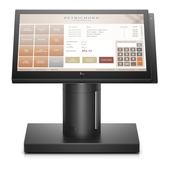
Product overview Standard features The HP Engage One Retail System is designed for long-term deployment within general retail, hospitality, and other markets. It includes the following features: ● Integrated All-in-One (AiO) form factor ● 14-inch diagonal display panel (wide-aspect ratio); FHD 1920 x 1080 resolution, sealed and chemically hardened, anti-glare;... - Page 10 Windows® 10 IoT Enterprise 2016 LTSB 64-bit – Windows 10 Professional 64-bit FreeDOS 2.0 – ● HP Engage One Advanced I/O Connectivity Base (optional) – 2 powered serial ports (0 V, 5 V, 12 V) – (2) 12 V powered USB ports –...
-
Page 11: Integrated Features
The integrated devices shown below are optional. Features 14-inch diagonal display panel (wide-aspect ratio); FHD HP Engage One 2 x 20 Customer-facing Display (CFD) 1920 x 1080 resolution, sealed and chemically hardened, anti-glare; anti-smudge HP Engage One Integrated Column Printer... -
Page 12: Stand Options
Stand options Options HP Engage One Rotate/Tilt Stand with Integrated Column Printer HP Engage One Rotate/Tilt Stand HP Engage One Fixed Position Stand NOTE: The stands are shown on a stability base. HP Engage One Basic I/O Connectivity Base components... -
Page 13: Hp Engage One Advanced I/O Connectivity Base Components
HP Engage One Advanced I/O Connectivity Base components Advanced components Cash drawer jack USB 3.0 ports (4) Powered USB 12 V ports (2) USB Type-C port Powered USB 24 V port RJ-45 network jack Power connector (10) Security cable slot... -
Page 14: Connecting An Ac Adapter To Power
Connecting an AC adapter to power To connect an AC adapter to the I/O connectivity base, connect one end of the power cord to the AC adapter (1) and the other end to a grounded AC outlet (2), and then connect the AC adapter to the power connector on the I/O connectivity base (3). -
Page 15: Locating The Engage One Power Button
Locating the Engage One power button The computer power button is located on the bottom right edge of the bezel. Locating the I/O connectivity base power button The I/O connectivity base power button is located on the underside of the I/O connectivity base. The head unit controls the I/O connectivity base. -
Page 16: Adjusting The Engage One Head Unit
Adjusting the Engage One head unit NOTE: The tilt and swivel features are only available on performance stands. You can tilt and swivel the computer head to set it to a comfortable viewing angle. There is a 10° tilt range that can be set between 50°... -
Page 17: Engage One Serial Number Location
Engage One serial number location Each computer has a unique serial number and a product ID number that are located on the exterior of the computer. Keep these numbers available for use when contacting customer service for assistance. I/O connectivity base serial number location Each I/O connectivity base has a unique serial number and a product ID number that are located on the exterior of the I/O connectivity base. -
Page 18: Illustrated Parts Catalog
Illustrated parts catalog NOTE: HP continually improves and changes product parts. For complete and current information on supported parts for your computer, go to http://partsurfer.hp.com, select your country or region, and then follow the on-screen instructions. Computer major components Item... - Page 19 Item Description Fan assembly Heat sink For use in models with 500 nit displays For use in models with 300 nit displays Power button board Speakers, left and right WLAN module Intel Dual Band Wireless-AC 8265 (vPro) Intel Dual Band Wireless-AC 8265 (non-vPro) Realtek RTL8723BE-VB 802.11 bgn 1x1 Wi-Fi + BT4.0 Combo Adapter (10) Memory modules (SODIMM, DDR4-2400)
-
Page 20: Peripherals
HP Engage One Fingerprint Reader HP Engage One Top Mount 2x20 CFD HP L8010t 10.1" Touch CFD HP L8010 10.1" Non-Touch CFD HP Engage One Column Printer, black or white I/O Connectivity Base Advanced (includes powered USBs) Basic (does not include powered USBs) -
Page 21: Cables And Adapters
Column printer cable, 23 cm, USB Type-B to Type-A Column printer cable, 50 cm, cash drawer 24V to Y (Hosiden/Type-B), powered USB cable (for use with HP POS Hybrid Printer, MICR with Imaging Module) 24V powered USB cable (power only), Hosiden... -
Page 22: Routine Care, Sata Drive Guidelines, And Disassembly Preparation
Computer operating guidelines and routine care Follow the guidelines below to properly set up and care for the computer: ● HP recommends a 17 mm clearance around the vents on the computer head unit and I/O connectivity base for heat dissipation. ●... -
Page 23: Msr Maintenance
The screws used in the computer are not interchangeable. They may have standard or metric threads and may be of different lengths. If an incorrect screw is used during the reassembly process, it can damage the unit. HP strongly recommends that all screws removed during disassembly be kept with the part that was removed, then returned to their proper locations. -
Page 24: Electrostatic Discharge Information
Batteries, battery packs, and accumulators should not be disposed of together with the general household waste. In order to forward them to recycling or proper disposal, please use the public collection system or return them to HP, their authorized partners, or their agents. Electrostatic discharge information A sudden discharge of static electricity from your finger or other conductor can destroy static-sensitive devices or microcircuitry. -
Page 25: Personal Grounding Methods And Equipment
● To avoid hand contact, transport products in static-safe containers such as tubes, bags, or boxes. Protect all electrostatic parts and assemblies with conductive or approved containers or packaging. ● ● Keep electrostatic sensitive parts in their containers until they arrive at static-free stations. Place items on a grounded surface before removing them from their container. -
Page 26: Recommended Materials And Equipment
Recommended materials and equipment Materials and equipment that are recommended for use in preventing static electricity include: ● Antistatic tape ● Antistatic smocks, aprons, or sleeve protectors Conductive bins and other assembly or soldering aids ● ● Conductive foam ● Conductive tabletop workstations with ground cord of one-megohm +/- 10% resistance ●... -
Page 27: Removal And Replacement Procedures
NOTE: HP continually improves and changes product parts. For complete and current information on supported parts for your computer, go to http://partsurfer.hp.com, select your country or region, and then follow the on-screen instructions. Adherence to the procedures and precautions described in this chapter is essential for proper service. After completing all necessary removal and replacement procedures, run the Diagnostics utility to verify that all components operate properly. -
Page 28: Attaching An I/O Connectivity Base To The Engage One
Attaching an I/O connectivity base to the Engage One You can attach an I/O connectivity base to the bottom of the computer’s stand. Prepare the computer for disassembly (Preparation for disassembly on page 19). Remove the cover on the I/O connectivity base by removing the four screws on the underside of the I/O connectivity base (1), and then lifting the cover off the I/O connectivity base (2). - Page 29 Place the I/O connectivity base onto the bottom of the stand (1), and then tighten the four screws on the underside of the I/O connectivity base (2) to secure the I/O connectivity base to the stand. Be sure that the USB Type-C power cable is routed through the gap between the back of the I/O connectivity base and the stand.
-
Page 30: Connecting A Standalone I/O Connectivity Base To The Engage One
Connecting a standalone I/O connectivity base to the Engage Prepare the computer for disassembly (Preparation for disassembly on page 19). Connect the USB Type-C power cable to the USB Type-C port on the underside of the stand’s column and to the USB Type-C power port on the I/O connectivity base. Connect the I/O connectivity base’s power supply to the I/O connectivity base and a grounded AC outlet. - Page 31 Remove the five screws on the underside of the I/O connectivity base (1) that secure the bottom plate to the I/O connectivity base, and then remove the bottom plate from the I/O connectivity base (2). Adjust the voltage select switch behind each serial port to the desired setting. Configuring the I/O connectivity base’s powered serial ports...
-
Page 32: Connecting A Standalone Optional Fingerprint Reader To The I/O Connectivity Base
Place the bottom plate onto the I/O connectivity base (1), and then secure the plate to the I/O connectivity base with the five screws (2). Reconnect the I/O connectivity base’s power cord and peripheral devices. Connecting a standalone optional fingerprint reader to the I/O connectivity base The optional fingerprint reader can be used as a standalone device or it can be attached to the I/O connectivity base. -
Page 33: Attaching An Optional Fingerprint Reader To The I/O Connectivity Base
Connect the fingerprint reader USB cable to a USB Type-A port on the I/O connectivity base. Reconnect the I/O connectivity base and computer power cords. Attaching an optional fingerprint reader to the I/O connectivity base The optional fingerprint reader can be used as a standalone device or it can be attached to the I/O connectivity base. - Page 34 Connect the USB cable to the fingerprint reader (1) and route the cable under the routing clip on the fingerprint reader (2). Remove the mounting screw (3) from the underside of the I/O connectivity base, and then attach the bracket on the fingerprint reader assembly to the underside of the I/O connectivity base (4) using the screw that was removed from the base and the short screw included in the kit.
-
Page 35: Removing And Attaching The Engage One Head Unit To The Stand
Removing and attaching the Engage One head unit to the stand Prepare the computer for disassembly (Preparation for disassembly on page 19). Insert a thin metal tool, such as a screwdriver, into the computer head unit release hole (1) on the stand to depress the release button, and then pull the head unit from the stand (2). -
Page 36: Mounting The Engage One Head Unit To A Wall
Mounting the Engage One head unit to a wall You can use an optional VESA mounting bracket to mount the computer head unit to a wall. Screws sizes are 241-I052-M004 for the security screw and 241-I042-M059 for the VESA mount screw. Prepare the computer for disassembly (Preparation for disassembly on page 19). - Page 37 Route the USB Type-C cable from the inside of the VESA bracket through the slot on the bracket’s rear cover (1), and then replace the rear cover (2). Connect the power cable from the VESA bracket to a wall outlet or I/O connectivity base. Mounting the Engage One head unit to a wall...
-
Page 38: Mounting The Engage One To A Counter Top
Mounting the Engage One to a counter top You can use an optional counter top mounting bracket to mount the computer head unit and column to a counter top. NOTE: The mounting bracket requires an 80 mm hole in the counter top. The thickness of the counter top must be 10 mm to 50 mm. - Page 39 Hold the top piece of the mounting bracket against the bottom of the column, route the cables through the hole in the mounting surface, and then place the column over the hole on the mounting surface. The bottom piece of the mounting bracket can be oriented in two ways, depending on the thickness of your mounting surface.
-
Page 40: Installing A Security Cable On The I/O Connectivity Base
Installing a security cable on the I/O connectivity base You can secure the I/O connectivity base to a fixed object with an optional Keyed Cable lock security cable extension and an optional security cable available from HP. NOTE: The security cable is sold separately as an aftermarket option kit only. -
Page 41: Installing A Security Cable On The Engage One Column
Installing a security cable on the Engage One column You can secure the I/O connectivity base to a fixed object with an optional Keyed Cable lock security cable extension and an optional security cable available from HP. NOTE: The security cable is sold separately as an aftermarket option kit only. -
Page 42: Installing A Security Screw On The Engage One Head Unit And Stand
Installing a security screw on the Engage One head unit and stand You can insert a tamper-resistant security screw into the computer’s column with a T-10 screwdriver to prevent access to the computer head unit’s release button. Remove the security screw from the bottom of the stand’s column. Install the security screw in the release button hole on the stand’s column. -
Page 43: Installing A Security Screw On The Engage One Head Unit And Vesa Mount
Installing a security screw on the Engage One head unit and VESA mount You can insert a tamper-resistant security screw into the computer’s VESA mount with a T-10 screwdriver to prevent access to the computer head unit’s release button. Press the rear cover release tab (1) on the VESA bracket, and then pull the rear cover off the VESA bracket (2). - Page 44 Lift stand base (2) to access the cables connected to the printer. Remove the cables from the clips on the printer base plate (1). Disconnect the cables from the printer and remove the cables and stand base (2). Rotate the column up to expose the head unit release hole (1). IMPORTANT: If a security screw is installed in the release hole, remove it to access the release button .
- Page 45 Insert a screwdriver into the release hole to depress the release button (2), and then pull the column up and off of the head unit (3). Remove the column printer door cover: Open the printer door (1). Remove the two Phillips head screws with the lock washers and bushings (2) from the top and bottom of the door cover.
- Page 46 Pull the door cover off of the door frame (3). Close the printer door. Remove the four Phillips screws that secure the stand cable connector housing, and then pull the cable cover away from the printer base. Chapter 4 Removal and replacement procedures...
- Page 47 Remove the three Phillips head screws that secure the printer engine to the bottom of the column. IMPORTANT: Do not remove any screws marked with 'P' on the base plate. Slide the printer engine about ¼ inch (0.6 cm) out of the column (1). Carefully remove the paper feed button from the opening in the column (2).
- Page 48 ● Holding the column with the door side up, ensure that the stand cable is on the far side of the alignment rod (1). While holding the paper feed actuator arm down, slide the printer engine into the column until the actuator arm is visible through hole (2).
-
Page 49: Removing The Display Panel
Removing the display panel You must remove the display panel from the computer head unit to access internal computer components. Prepare the computer for disassembly (Preparation for disassembly on page 19). Remove the computer head unit from the stand (Removing and attaching the Engage One head unit to the stand on page 27). -
Page 50: System Board Components
Rotate the display panel over the top of the computer head unit and onto a flat surface covered by a soft clean cloth. IMPORTANT: The touch and WLAN cables will still be connected between the top of the display panel and the top of the computer head unit. -
Page 51: Installing A 2 X 20 Customer-Facing Display (Cfd)
Installing a 2 x 20 customer-facing display (CFD) Prepare the computer for disassembly (Preparation for disassembly on page 19). Remove the computer head unit from the stand (Removing and attaching the Engage One head unit to the stand on page 27). - Page 52 Install the two screws that attach the CFD to the computer head unit (1), and then connect the CFD cable to the connector on the system board (2). IMPORTANT: Make sure the entire CFD cable is pulled all the way through the head unit routing channel before installing the CFD so that the cable does not get pinched between the CFD and the head unit.
-
Page 53: Memory Modules
Memory modules The computer comes with at least one preinstalled double data rate 4 synchronous dynamic random access memory (DDR4-SDRAM) small outline dual in-line memory module (SODIMM). There are two memory sockets on the system board that can be populated with up to 32 GB of memory. DDR4-SDRAM SODIMMs For proper system operation, the memory modules must be 1.2 volt DDR4-SDRAM SODIMMs and adhere to the following specifications:... - Page 54 Prepare the computer for disassembly (Preparation for disassembly on page 19). Remove the computer head unit from the stand (Removing and attaching the Engage One head unit to the stand on page 27). Remove the display panel from the computer head unit (Removing the display panel on page Remove the shield over the memory modules by pulling the tab on the shield up (1), and then lifting the shield from the system board (2).
- Page 55 To install a memory module, slide the new memory module into the socket at approximately a 30° angle (1), and then press the memory module down into the socket (2) so that the latches lock it in place. NOTE: A memory module can be installed in only one way. Match the notch on the module with the tab on the memory socket.
-
Page 56: Removing And Installing An M.2 Solid-State Drive (Ssd)
Removing and installing an M.2 solid-state drive (SSD) IMPORTANT: If you are replacing an SSD , be sure to back up the data from the old SSD so that you can transfer the data to the new SSD. To remove and install an M.2 storage device: Prepare the computer for disassembly (Preparation for disassembly on page 19). -
Page 57: Removing The Wlan Module
Removing the WLAN module Description 802.11 a/b/g/n + Bluetooth 4.0, 2x2 802.11 a/b/g/n + Bluetooth 4.0, 2x2 (for use only in Indonesia) Intel Dual Band Wireless-AC 8260 The WLAN module is secured with one screw and has two connected antennas. To remove the WLAN module: Prepare the computer for disassembly (Preparation for disassembly on page... - Page 58 To install a WLAN module, slide the connector end of the module into the system board connector (1), then secure the other end of the module to the system board with the screw (2), and then connect the two cables from the display panel to the connectors on the WLAN module (3). IMPORTANT: The WLAN cables and connectors are labeled 1 and 2.
-
Page 59: Removing The Heat Sink
Removing the heat sink The heat sink is secured to the system board, under the heat sink shield. To remove the heat sink: Prepare the computer for disassembly (Preparation for disassembly on page 19). Remove the computer head unit from the stand (Removing and attaching the Engage One head unit to the stand on page 27). -
Page 60: Removing The Fan Assembly
Removing the fan assembly The fan assembly is secured with four screws and has one cable. To remove the fan: Prepare the computer for disassembly (Preparation for disassembly on page 19). Remove the computer head unit from the stand (Removing and attaching the Engage One head unit to the stand on page 27). -
Page 61: Removing The Speakers
Removing the speakers The computer uses two separate speakers located on the left and right sides. Each speaker has a cable that connects to a separate connector. To remove the speakers: Prepare the computer for disassembly (Preparation for disassembly on page 19). -
Page 62: Removing The Power Button Board
Removing the power button board The power button board is secured with one Phillips screws. To remove the power button board: Prepare the computer for disassembly (Preparation for disassembly on page 19). Remove the computer head unit from the stand (Removing and attaching the Engage One head unit to the stand on page 27). -
Page 63: Removing The Msr (Magnetic Stripe Reader)
Removing the MSR (Magnetic Stripe Reader) The MSR consists of two main components that are connected together into one assembly. To remove the MSR assembly: Prepare the computer for disassembly (Preparation for disassembly on page 19). Remove the computer head unit from the stand (Removing and attaching the Engage One head unit to the stand on page 27). -
Page 64: Msr Configuration
Lift the board straight up and off the posts (3). Remove the MSR (assembly from the computer head unit. MSR configuration LED swipe code: green = good; red = bad Single beep = good read; three beeps = good read on all three tracks For information about MSR encryption, see Solving retail system-specific problems on page 103. - Page 65 Swipe a credit card. Disable, Release, and Close [D/R/C] the test application. TIP: USB HID mode requires an application that uses OPOS or JPOS drivers to confirm that the MSR is able to read the data. Non-encrypted or encrypted: HID M ATIVE DRIVER Human Interface Devices\USB Input Device USB\VID_03F0&PID_0457...
-
Page 66: Removing The Msr Led Board
Removing the MSR LED board The MSR LED board is a separate component from the MSR. It is secured with one Phillips screw. To remove the MSR LED board: Prepare the computer for disassembly (Preparation for disassembly on page 19). Remove the computer head unit from the stand (Removing and attaching the Engage One head unit to the stand on page... -
Page 67: Removing The System Board
Removing the system board NOTE: All system board spare part kits include replacement thermal material. System boards include an integrated Intel processor. The system board is secured with six screws. Additionally, the system board is secured by the display connector from the rear of the display. To remove the system board: Prepare the computer for disassembly (Preparation for disassembly on page... - Page 68 Disconnect the following cables from the system board: (1) MSR LED board (2) Fingerprint reader board (3) Right speaker (4) Power button board (5) RTC battery (6) Left speaker (7) Fan assembly Remove the 6 Phillips screws that secure the system board to the computer head unit (1). Remove the system board from the computer head unit (2).
-
Page 69: System Board Callouts
System board callouts Sys Bd Label Color Component Sys Bd Label Color Component White RTC battery MSR LED White MSR LED board CMOS Yellow Reset CMOS Black Power button board CPU FAN Black Fan assembly Black Solid-state drive DIMM1 Black Memory module SPKR_L Black... -
Page 70: Removing The Antennas
Removing the antennas The wireless antenna cables connect from the WLAN module to antennas at the top of the computer. To remove the antennas: Prepare the computer for disassembly (Preparation for disassembly on page 19). Remove the computer head unit from the stand (Removing and attaching the Engage One head unit to the stand on page 27). -
Page 71: Using The Column Printer
Using the column printer The column printer is an optional component that may be included with your system. Standard features Standard features Interface Memory/firmware 8 MB flash memory, History EEROM, 4k buffer Energy-savings Option to configure printer to enter low-power (1 watt) idle state if no data is received after user-specified number of minutes Resident character sets PC code pages 437 (US), 720 (Arabic), 737 (Greek), 775 (Baltic), 850 (Multilingual), 852... -
Page 72: When To Change The Receipt Paper
When to change the receipt paper Change the paper when it is near the end of the roll or when the roll is empty. When the paper is low, you must monitor usage to avoid running out part of the way through a transaction. When the roll is empty, you must load a new roll immediately or data may be lost. -
Page 73: Thermal Paper Specifications
Qualified paper grades Contact the manufacturer of your choice to order paper. HP recommends the following paper grades produced by their respective manufacturers. There are a number of paper manufacturers qualified to provide this paper, provided the POS paper rolls are from the recommended grades for monochrome (black ink) paper. -
Page 74: Troubleshooting The Printer
The printer is generally trouble-free; however, unexpected conditions may arise. Refer to the following sections to diagnose and solve these printer conditions. To resolve complex issues, you may need to contact an authorized HP service representative. Chapter 5 Using the column printer... -
Page 75: Printer Tone And Green Led
LED stops blinking. The knife is unable to return to Stop using the printer. Contact your authorized HP the home position. service representative. Green LED, slow steady Other problems may be Stop using the printer. -
Page 76: Printer Does Not Function
One side of receipt is missing. This indicates a serious Stop using the printer. Contact your authorized HP condition with the printer service representative. electronics. NOTE: Using nonrecommended paper may damage the printhead and void the warranty. -
Page 77: Latch Failsafe
Because of the way the printer sits while in use, it is likely there will be buildup of paper and other debris from the knife. HP recommends that you keep the printer in working order by periodically cleaning the debris from the printer. -
Page 78: Cable Routing Configurations
Cable routing configurations Cable matrix for Engage One with integrated column printer and basic I/O connectivity base Cables Column printer AC power cord I/O connectivity base mini USB Type-B to USB Type-A data cable Column printer AC adapter cable I/O connectivity base USB Type-C cable Cash drawer cable (purchased separately with cash I/O connectivity base 120 W AC power cord drawer) -
Page 79: Cable Matrix For Engage One With Integrated Column Printer And Advanced I/O Connectivity Base
Cable matrix for Engage One with integrated column printer and advanced I/O connectivity base Cables I/O connectivity base 180 W AC power cord Column printer 24 V PUSB power and data Y cable Cash drawer cable (purchased separately with cash I/O connectivity base USB Type-C cable drawer) Column printer cash drawer cable... -
Page 80: Cable Matrix For Engage One Without I/O Connectivity Base
Cable matrix for Engage One without I/O connectivity base Cables PC power cord Chapter 6 Cable routing configurations... -
Page 81: Cable Matrix For Engage One With I/O Connectivity Base
Cable matrix for Engage One with I/O connectivity base Cables Basic I/O connectivity base 120 W AC power cord USB-C mini dock 90 W AC power cord I/O connectivity base USB Type-C cable USB-C mini dock captive USB Type-C cable Advanced I/O connectivity base 180 W AC power cord NOTE: In the European region, the USB-C mini dock is sold as an aftermarket option kit only. -
Page 82: Cable Matrix For Engage One With Basic I/O Connectivity Base And Standalone Printer
Cable matrix for Engage One with basic I/O connectivity base and standalone printer Cables Printer AC power cord Printer USB Type-A to Type-B data cable Basic I/O connectivity base 120 W AC power cord Basic I/O connectivity base USB Type-C cable Printer serial data cable IMPORTANT: Connect either the serial data cable (3) or the USB Type-A data cable (4) between the I/O connectivity base and the... -
Page 83: Cable Matrix For Engage One With Advanced I/O Connectivity Base And Standalone Printer
Cable matrix for Engage One with advanced I/O connectivity base and standalone printer Cables Printer 24 V PUSB power and data “Y” cable Printer serial data cable Advanced I/O connectivity base 180 W AC power adapter Advanced I/O connectivity base USB Type-C cable cord Printer 24 V PUSB power cable IMPORTANT:... -
Page 84: Configuring The Software
Configuring optional HP integrated peripheral modules To configure the integrated USB peripheral, refer to the HP Point of Sale Configuration Guide (available in English only). The guide is located with the documentation on your retail computer and at http://www.hp.com/support. To access the guide on the retail computer, select Start, and then select HP Point of Sale Information. -
Page 85: Computer Setup (F10) Utility
Computer Setup (F10) Utility Computer Setup (F10) Utilities Use Computer Setup (F10) Utility to do the following: ● Change factory default settings. View the system configuration, including settings for processor, graphics, memory, audio, storage, ● communications, and input devices. ● Modify the boot order of bootable devices such as hard drives, optical drives, or USB flash media devices. - Page 86 A choice of four headings appears in the Computer Setup Utilities menu: Main, Security, Advanced, and UEFI Drivers. NOTE: Selecting UEFI Drivers restarts the computer into the 3rd party option ROM management application. You can access this application directly by pressing during startup.
-
Page 87: Computer Setup-Main
● Build ID ● Product Family ● System Board ID ● System Board CT System Diagnostics Starts HP PC Hardware Diagnostics UEFI. Lets you perform the following functions: ● Memory Test ● Hard Drive Check ● Language Update System BIOS Displays current BIOS information. - Page 88 Lets you configure BIOS updates through the network. ● Check for Update on Next Reboot ● BIOS Source – select the source of the BIOS update from either HP.com or a custom URL. ● Automatic BIOS Update Setting – select how BIOS is updated. NOTE: BitLocker Drive Encyption (BDE) must be temporarily suspended to be able to flash the BIOS.
-
Page 89: Computer Setup-Security
Table 8-1 Computer Setup—Main (continued) Option Description Replicated Setup Backup current settings to USB device Saves system configuration to a formatted USB flash media device. Restore current settings from USB device Restores system configuration from a USB flash media device. Save Custom Defaults Saves the current system configuration settings as the default. - Page 90 Enabled: When this box is checked, the HP Sure Start will continue to verify the integrity of the BIOS in System Flash each time the system is in a Sleep, Hibernate, or Off state. Additionally, the HP Sure Start will verify the integrity of the BIOS in System Flash on each Warm Boot (Windows Restart).
-
Page 91: Computer Setup-Advanced
Table 8-2 Computer Setup—Security (continued) Option Description Hard Drive Utilities Save/Restore MBR of System Hard Drive Enable to save the Master Boot Record (MBR) of the hard drive. If the MBR gets changed, the user is prompted to authorize restoring the MBR. DriveLock Allows you to assign or modify a master or user password for hard drives. - Page 92 Table 8-3 Computer Setup—Advanced (for advanced users) (continued) Option Description ● After Power Loss (off/on/previous state). Default is Power off. Setting this option to: Power off—causes the computer to remain powered off when power is restored. ○ ○ Power on—causes the computer to power on automatically as soon as power is restored. ○...
- Page 93 Table 8-3 Computer Setup—Advanced (for advanced users) (continued) Option Description Lets you delete any previously loaded custom boot keys. Clearing keys will disable secure boot. Default is disabled. Reset Security Boot keys to factory defaults Default is disabled. Enable MS UEFI CA key Lets you enabled the Certification Authority key.
- Page 94 Table 8-3 Computer Setup—Advanced (for advanced users) (continued) Option Description Headphone output (does not affect external speakers) Select to allow sound to go to headphones. Default is enabled. Increase Idle Fan Speed(%) Sets idle fan speed percentage. This setting only changes the minimum fan speed. The fan is still automatically controlled.
-
Page 95: Recovering The Configuration Settings
Table 8-3 Computer Setup—Advanced (for advanced users) (continued) Option Description Enabling this feature reduces the power of the system as much as possible in the S5 state. Power is removed from the wake up circuitry, the expansion slots, and any management features while in S5. Default is disabled. -
Page 96: Post Error Messages And Diagnostic Front Panel Leds And Audible Codes
POST error messages and diagnostic front panel LEDs and audible codes This appendix lists the error codes, error messages, and the various indicator light and audible sequences that you may encounter during Power-On Self-Test (POST) or computer restart, the probable source of the problem, and steps you can take to resolve the error condition. - Page 97 Control panel message Description Recommended action RTC (real-time clock) battery may need to problem persists, replace the RTC battery. See be replaced. the Removal and Replacement section for instructions on installing a new battery. 008–Microcode Patch Error Processor is not supported by the BIOS. Upgrade BIOS to proper version.
- Page 98 Run the Drive Protection erroneous error message.) System test under using F2 Diagnostics when booting the computer. Apply hard drive firmware patch if applicable. (Available at http://www.hp.com/support.) Chapter 9 POST error messages and diagnostic front panel LEDs and audible codes...
- Page 99 System test under using F2 Diagnostics when booting the computer. Apply hard drive firmware patch if applicable. (Available at http://www.hp.com/support.) Back up contents and replace hard drive. 309 – 30C: Hard Disk 3–6: SMART Hard Drive Hard drive is about to fail. (Some hard drives...
- Page 100 500–BIOS Recovery A system BIOS recovery has occurred. Not applicable. 60x-HP Battery Alert The system has detected the storage capacity For optimal performance, replace the battery. of the battery stated below to be very low. 70x-Wireless Mode Not Supported The system has detected a wireless module Replace with a supported module.
-
Page 101: Interpreting System Validation Diagnostic Front Panel Leds And Audible Codes
Control panel message Description Recommended action 910–Filter Warning Airflow filter is dirty. Replace the airflow filter. 90B-Fan Failure The system has detected that a cooling fan is Reseat fan. not operating correctly. Reseat fan cable. Replace fan. 90D-System Temperature Thermal shutdown occurred. The system BIOS Make sure system has proper airflow. - Page 102 Number of long beeps/blinks Error category Thermal System board Patterns of blink/beep codes are determined by using the following parameters: ● 1 second pause occurs after the last major blink. 2 second pause occurs after the last minor blink. ● ●...
-
Page 103: 10 Password Security And Resetting Cmos
10 Password security and resetting CMOS This computer supports security password features, which can be established through the Computer Setup Utilities menu. This computer supports two security password features that are established through the Computer Setup Utilities menu: setup password and power-on password. When you establish only a setup password, any user can access all the information on the computer except Computer Setup. -
Page 104: Changing A Setup Or Power-On Password
Shut down the operating system properly, then turn off the computer and any external devices, and disconnect the power cord from the power outlet. With the power cord disconnected, press the power button again to drain the system of any residual power. -
Page 105: Deleting A Setup Or Power-On Password
When the key icon appears, type your current password, a slash (/) or alternate delimiter character, your new password, another slash (/) or alternate delimiter character, and your new password again as shown: current password/new password/new password NOTE: Type the new password carefully since the characters do not appear on the screen. Press Enter. - Page 106 CAUTION: Pushing the CMOS button will reset CMOS values to factory defaults. It is important to back up the computer CMOS settings before resetting them in case they are needed later. Back up is easily done through Computer Setup. See Computer Setup (F10) Utility on page 77 for information on backing up the CMOS settings.
-
Page 107: Using Hp Pc Hardware Diagnostics (Uefi)
11 Using HP PC Hardware Diagnostics (UEFI) HP PC Hardware Diagnostics is a Unified Extensible Firmware Interface (UEFI) that allows you to run diagnostic tests to determine whether the computer hardware is functioning properly. The tool runs outside the operating system so that it can isolate hardware failures from issues that are caused by the operating system or other software components. -
Page 108: Using Remote Hp Pc Hardware Diagnostics (Uefi) Settings (Select Products Only)
Set the location for downloading the diagnostic tools. This feature provides access to the tools from the HP website or from a server that has been preconfigured for use. Your computer does not require the traditional local storage (such as a disk drive or USB flash drive) to run remote diagnostics. -
Page 109: 12 Troubleshooting Without Diagnostics
To assist you in resolving problems online, HP Instant Support Professional Edition provides you with self- solve diagnostics. If you need to contact HP support, use HP Instant Support Professional Edition's online chat feature. Access HP Instant Support Professional Edition at: http://www.hp.com/go/ispe. -
Page 110: Helpful Hints
HP experts. If it becomes necessary to call for technical assistance, be prepared to do the following to ensure that your service call is handled properly: ●... -
Page 111: Solving Retail System-Specific Problems
Solving retail system-specific problems The issues listed in this section are specific to features available in this retail system. IMPORTANT: Always be sure to load the latest BIOS and drivers, available from http://support.hp.com/. Powered serial ports do not have power. Cause Solution Ports are not correctly configured. -
Page 112: Solving General Problems
Cause Solution The new MSR needs to be configured with the system settings Connect the old MSR (the one being replaced). using HP USB Mini Magnetic Stripe Reader (MSR) Configuration Start HP magnetic stripe reader configuration utility Software. (http://h20564.www2.hp.com/hpsc/swd/public/detail? swItemId=ir_125989_1&swEnvOid=4047). - Page 113 Cannot access the Computer Setup (F10) Utility when booting the computer. Cause Solution Follow the Windows instructions for rebooting the computer into the Computer Setup (F10) Utility. Computer appears locked up and will not turn off when the power button is pressed. Cause Solution Software control of the power switch is not functional.
- Page 114 In case of forgotten password, power loss, or computer malfunction, you must manually disable the Smart Cover lock . A key to unlock the Smart Cover Lock is not available from HP. Keys are typically available from a hardware store.
- Page 115 Poor performance. Cause Solution Some software applications, especially games, are stressful on Lower the display resolution for the current application or the graphics subsystem. consult the documentation that came with the application for suggestions on how to improve performance by adjusting parameters in the application.
-
Page 116: Solving Printer Problems
System does not power on and the LEDs on the front of the computer are not flashing. Cause Solution If the 5V_aux light on the system board is off, then replace the power supply. Replace the system board. Solving printer problems If you encounter printer problems, see the documentation that came with the printer and to the common causes and solutions listed in the following table. -
Page 117: Solving Hardware Installation Problems
Printer will not print. Cause Solution The printer may be out of paper. Check the paper tray and refill it if it is empty. Solving hardware installation problems You may need to reconfigure the computer when you add or remove hardware, such as an additional drive or expansion card. -
Page 118: Solving Network Problems
NOTE: DIMM1 or XMM1 must always be installed. DIMM1 must be installed before DIMM3. Replace third-party memory with HP memory. Replace the system board. Solving network problems Some common causes and solutions for network problems are listed in the following table. These guidelines do not discuss the process of debugging the network cabling. - Page 119 Network status link light never flashes. NOTE: The network status light is supposed to flash when there is network activity. Cause Solution Network controller is not set up properly. Check for the device status within Windows, such as Device Manager for driver load and the Network Connections applet within Windows for link status.
-
Page 120: Solving Memory Problems
Management Engine (ME) settings). To avoid damage to the DIMMs or the system board, you must unplug the computer power cord before attempting to reseat, install, or remove a memory module. For those systems that support ECC memory, HP does not support mixing ECC and non-ECC memory. Otherwise, the computer will not boot the operating system. - Page 121 Cause Solution Memory is installed incorrectly or is bad. Reseat DIMMs. Power on the system. Replace DIMMs one at a time to isolate the faulty module. Replace third-party memory with HP memory. Replace the system board. Solving memory problems 113...
-
Page 122: Solving Usb Flash Drive Problems
Solving USB flash drive problems If you encounter USB flash drive problems, common causes and solutions are listed in the following table. USB flash drive is not seen as a drive letter in Windows. Cause Solution The drive letter after the last physical drive is not available. Change the default drive letter for the flash drive in Windows. - Page 123 Unable to connect to the Internet. Cause Solution Cable/DSL service is not available or has been interrupted due to Try connecting to the Internet at a later time or contact your ISP. bad weather. (If the cable/DSL service is connected, the “cable” LED light on the front of the cable/DSL modem will be on.) The CAT5 UTP cable is disconnected.
-
Page 124: Solving Software Problems
If you have installed an operating system other than the factory-installed operating system, check to be sure it is supported on the system. If you encounter software problems, see the applicable solutions listed in the following table. Computer will not continue and the HP logo does not display. Cause Solution ROM issue - POST error has occurred. -
Page 125: 13 System Backup And Recovery
Use HP Recovery Manager to create HP Recovery media after you successfully set up the computer. This step creates a backup of the HP Recovery partition on the computer. The backup can be used to reinstall the original operating system in cases where the hard drive is corrupted or has been replaced. For... - Page 126 DVD-R, DVD+R, DVD-R DL, or DVD+R DL discs. Do not use rewritable discs such as CD±RW, DVD±RW, double-layer DVD±RW, or BD-RE (rewritable Blu-ray) discs; they are not compatible with HP Recovery Manager software. Or, instead, you can use a high- quality blank USB flash drive.
-
Page 127: Using Windows Tools
HP Recovery Manager software allows you to recover the computer to its original factory state by using the HP Recovery media that you either created or that you obtained from HP, or by using the HP Recovery partition (select products only). If you have not already created recovery media, see... -
Page 128: Using The Hp Recovery Partition (Select Products Only)
117. ● If your computer does not allow the creation of HP Recovery media or if the HP Recovery media does not work, you can obtain recovery media for your system from support. See the Worldwide Telephone Numbers booklet included with the computer. You can also find contact information from the HP website. -
Page 129: Changing The Computer Boot Order
Changing the computer boot order If your computer does not restart in HP Recovery Manager, you can change the computer boot order, which is the order of devices listed in BIOS where the computer looks for startup information. You can change the selection to an optical drive or a USB flash drive. -
Page 130: Appendix A Power Cord Set Requirements
Power cord set requirements The power supplies on some computers have external power switches. The voltage select switch feature on the computer permits it to operate from any line voltage between 100-120 or 220-240 volts AC. Power supplies on those computers that do not have external power switches are equipped with internal switches that sense the incoming voltage and automatically switch to the proper voltage. -
Page 131: Country-Specific Requirements
Country-specific requirements Additional requirements specific to a country are shown in parentheses and explained below. Country Accrediting Agency Country Accrediting Agency Australia (1) EANSW Italy (1) Austria (1) Japan (3) METI Belgium (1) CEBC Norway (1) NEMKO Canada (2) Sweden (1) SEMKO Denmark (1) DEMKO... -
Page 132: Appendix B Statement Of Memory Volatility
Intel-based and AMD-based system boards contain nonvolatile memory subcomponents as originally shipped from HP, assuming that no subsequent modifications have been made to the system and assuming that no applications, features, or functionality have been added to or installed on the system. - Page 133 If a DriveLock password is set, select the Security menu, and scroll down to Hard Drive Utilities under the Utilities menu. Select Hard Drive Utilities, select DriveLock, then uncheck the checkbox for DriveLock password on restart. Select OK to proceed. Select the Main menu, and then select Reset BIOS Security to factory default.
-
Page 134: Nonvolatile Memory Usage
HP Sure Start only) backup of The content is managed Embedded Controller. critical System solely by the HP Sure Start BIOS code, EC Embedded Controller. firmware, and critical computer configuration data for select... - Page 135 512 KByte flash Stores Fingerprint reader memory is Only a digitally signed (select products fingerprint programmed by user application can make the only) templates. enrollment in HP call to write to the flash. ProtectTools Security Manager. Nonvolatile memory usage 127...
-
Page 136: Questions And Answers
HP has provided options in Computer Setup (BIOS) to allow you to run in legacy BIOS, if required by the operating system. Examples of this requirement would be if you upgrade or downgrade the OS. -
Page 137: Using Hp Sure Start (Select Models Only)
BIOS to its previously safe state, without user intervention. Those select computer models ship with HP Sure Start configured and enabled. HP Sure Start is configured and already enabled so that most users can use the HP Sure Start default configuration. The default configuration can be customized by advanced users. -
Page 138: 130 Appendix C Specifications
Specifications Head unit (without MSR or stand) 336.2 mm 13.2 in Length 216.4 mm 8.5 in Depth 17.6 mm 0.7 in Height Rotate/tilt stand & fixed position stand/Column printer 96.0 mm 3.8 in Length 96.0 mm 3.8 in Depth 220.0 mm/260.0 mm 8.7 in/10.2 in Height Retail I/O Connectivity Base... - Page 139 Operating Line Frequency 47-63 Hz This system utilizes an active power factor corrected power supply. This allows the system to pass the CE mark requirements for use in the countries of the European Union. The active power factor corrected power supply also has the added benefit of not requiring an input voltage range select switch.
-
Page 140: Index
AC adapter 6 illustrated 11 counter top mount 30 removing 51 password country power cord set helpful hints 102 clearing 95 requirements 123 HP PC Hardware Diagnostics (UEFI) power-on 95 Customer Support 101 using 99 setup 95 132 Index... - Page 141 passwords 96, 97 peripherals 12 safety and comfort 101 Windows 10 POST error messages 88 screws, correct size 15 backup and restore 117 power button security cable WLAN module computer 7 attaching to computer 33 illustrated 11 I/O connectivity base 7 attaching to I/O connectivity removing 49 power button board...
Need help?
Do you have a question about the Engage One Retail System 141 and is the answer not in the manual?
Questions and answers