Table of Contents
Advertisement
Operation Manual
Electric Airless Paint Sprayer
DP-X6
DP-X6V
DP-X6H
Important Safety Instructions
Read all warnings and instructions in this manual, related manuals, and on
the unit. Be familiar with the controls and the proper usage of the equipment.
Save these instructions. Read carefully and practice good safety habits.
www.dpairless.com
Advertisement
Table of Contents

Related Manuals for Dino-Power DP-X6


Summary of Contents for Dino-Power DP-X6
- Page 1 Operation Manual Electric Airless Paint Sprayer DP-X6 DP-X6V DP-X6H Important Safety Instructions Read all warnings and instructions in this manual, related manuals, and on the unit. Be familiar with the controls and the proper usage of the equipment. Save these instructions. Read carefully and practice good safety habits.
-
Page 2: Before You Spray
Before You Spray FIRE AND EXPLOSION HAZARD DP-X6/X6V/X6H Models: • Use only non-flammable or water-based/oil-based materials, or non-flammable paint thinners. Do not use materials having flash points lower than 100° F (38° C). This includes, but is not limited to, acetone, xylene, toluene, or naphtha. -
Page 3: Table Of Contents
Contents Contents Before You Spray.......................... 1 Warnings............................3 Know Your Sprayer........................6 Setup..............................7 Start Up............................9 Pressure Relief Procedure.....................9 How to Spray..........................12 Adjust Pressure Control....................... 13 Spray Techniques......................... 13 Clear Tip Clog........................14 Cleanup............................15 Storage............................17 Reference............................19 Spray Tip Selection....................... 19 Cleaning Fluid Compatibility.................... -
Page 4: Warnings
Flammable fumes, such as solvent and paint fumes, in work area can ignite or explode. To help prevent fire and explosion: DP-X6/X6V/X6H Models: • Do not spray or clean with materials having flash points lower than 100°F (38° C). Use only non-flammable or water-based materials, or non-flammable paint thinners. - Page 5 Warnings SKIN INJECTION HAZARD High-pressure spray is able to inject toxins into the body and cause serious bodily injury. In the event that injection occurs, get immediate surgicaltreatment. • Do not aim the gun at, or spray any person or animal. •...
- Page 6 Warnings PRESSURIZED ALUMINUM PARTS HAZARD Use of fluids that are incompatible with aluminum in pressurized equipment can cause serious chemical reaction and equipment rupture. Failure to follow this warning can result in death, serious injury, or propertydamage. • Do not use 1,1,1-trichloroethane, methylene chloride, other halogenated hydrocarbon solvents or fluids containing such solvents.
-
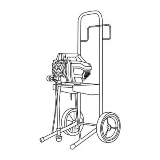
Page 7: Know Your Sprayer
Know Your Sprayer DP-X6 Prime/Spray Valve Gun Fluid Filter(inside handle) Pressure Control Knob Pump ON/OFF Switch Pump Fluid Outlet Fitting Suction Tube High Pressure Hose Drain Tube Suction Filter Airless Spray Gun Power Cord Reversible Spray Tip Suction Tube Drip Cup... - Page 8 Know Your Sprayer Technical Specifications: Model No. DP-X6/X6V/X6H Pressure Controlling Mechanical Motor Power 650W Max. Flow Rate 1.4L/min 0.36GPM Max. Tip Size 0.019” Max. Pressure 200bar/2900psi Max. Hose Length Reminding Tips: 1. Clean the pump / hose / spray gun / spray tip throughly everyday when you finish your painting job.
-
Page 9: Setup
Setup Start Up Setup When unpacking sprayer for the first time or after long term storage perform setup procedure. Assemble Your Sprayer Connect DP airless hose to fluid outlet. Use wrench to tighten securely. Turn pressure control knob all the way left (counter-clockwise) to lowest set- ting. -
Page 10: Start Up
Start Up Start Up Turn pressure control knob to lowest setting. Pressure Relief Procedure Follow the Pressure Relief Procedure whenever you see this symbol. Put drain tube into a waste pail and turn Prime/Spray valve in PRIME position (drain) to relieve pressure. This equipment stays pressurized until pressure is manually relieved. - Page 11 Start Up If you suspect the spray tip or hose Turn Prime/Spray valve is clogged or that pressure has not down to PRIME position. been fully relieved: VERY SLOWLY loosen the tip guard retaining nut or the hose end coupling to relieve pressure gradually.
- Page 12 Start Up How to Spray 10. When sprayer starts pumping, flushing NOTE: Some fluids may prime faster solvent and air bubbles will be purged if the ON/OFF Switch is momentarily from system. Allow fluid to flow out of turned off so the pump can slow and drain tube, into waste pail, for 30 to 60 stop.
-
Page 13: How To Spray
How to Spray How to Spray Spray Tip Installation Spray tip must be pushed all the way To prevent spray tip leaks make certain into the tip guard. spray tip and tip guard are installed properly. Perform Pressure Relief Procedure, page 9. Engage trigger lock. -
Page 14: Adjust Pressure Control
To select function, align symbol on pressure control knob with setting indicator on sprayer. Tip and Pressure Selection See table for recommended spray pressure for your material. Refer to paint (material) can for manufacturer’s recommendations. Maximum tip hole sizes supported by the sprayer: DP-X6: 0.019 in. (0.48 mm) Coatings Interior Stains/ Interior &... -
Page 15: Clear Tip Clog
How to Spray How to Spray Triggering Gun • Material may need to be thinned. If material needs to be thinned follow Pull trigger after starting stroke. Release manufacturer’s recommendations. trigger before end of stroke. Gun must be Clear Tip Clog moving when trigger... -
Page 16: Cleanup
Cleanup Cleanup Cleanup Cleaning the sprayer after each use results in Place empty waste and flushing fluid a trouble free start up the next time the pails side by side. sprayer is used. Place suction tube in flushing fluid. Use water for water based paint and mineral spirits or compatible oil-based flushing solvent for oil-based paint. - Page 17 Cleanup 11. Turn ON/OFF switch to OFF position. Turn Prime/Spray valve down to PRIME position. NOTE: Step 12 is for returning paint in 16. Turn ON/OFF switch to OFF position. hose to paint pail. One 50 ft (15 m) hose holds approximately 1 quart (1 liter) of paint.
-
Page 18: Storage
Storage Storage With proper storage, the sprayer will be ready Engage trigger lock. to use the next time it is needed. Leave gun attached to hose. Short Term Storage Remove tip and guard and clean with water or flushing fluid and a brush. (up to 2 days) Wipe paint off outside of gun using a soft cloth moistened with water or flush-... - Page 19 Storage Turn Prime/Spray valve down Leave gun attached to hose. to PRIME position. Remove tip and guard and clean with water or flushing fluid and a brush. 10. Wipe paint off outside of gun using a soft cloth moistened with water or flush- ing fluid.
-
Page 20: Reference
Reference Reference Understanding Tip Number The last three digits of tip number (i.e.:413) Spray Tip Selection contain information about hole size and fan width on surface when gun is held 12 in. (30.5 cm) from surface being sprayed. Selecting Tip Size First digit when doubled Spray tips come in a variety of hole sizes for 413 tip has... -
Page 21: Cleaning Fluid Compatibility
Reference Cleaning • To avoid fluid splashing back on your skin or into your eyes, always aim gun Fluid at inside wall of pail. Compatibility Static Grounding Instructions (Oil-Based materials) The equipment must be grounded to Oil- or Water-Based Materials reduce the risk of static sparking and electric shock. - Page 22 Reference Quick Reference Ref. Name Description • In PRIME position directs fluid to draintube. Prime/Spray Valve • In SPRAY position directs pressurized fluid to paint hose. • Automatically relieves system pressure in over- pressure situations. Increases (clockwise) and decreases Pressure Control Knob (counter-clockwise) fluid pressure in pump, hose, and spray gun.
-
Page 23: Maintenance
Maintenance Reference Maintenance Routine maintenance is important to ensure proper operation of your sprayer. Activity Interval Inspect motor shroud openings for blockage. Daily or each time you spray Inspect/clean filter, fluid inlet strainer, and gun filter. Daily or each time you spray NOTIC Protect the internal drive parts of this sprayer from water. - Page 24 Maintenance Take down the left and right housings. Remove the connection bolts between the pump and the supporting frame. Remove the wire connection between motor and electroncial control board and between pressure control valve and electronical control board.
- Page 25 Maintenance Inlet Valve Removal and Installation Piston Rod and V-packings If you suspect that the inlet valve is clogged Disassembling or stuck, remove the valve assembly and clean or replace. 1. Remove the pump(page 22). Remove suction tube or hopper 2.
- Page 26 Maintenance Troubleshooting Piston Rod and V-packings Installation 1. Put the O-ring onto the piston rod. 2. Put the piston rod into the pump body. 3. Tighten the copper sleeve.
-
Page 27: Troubleshooting
Troubleshooting Troubleshooting Check everything in this Troubleshoot- ing Table before you bring the sprayer to an authorized service center. Follow Pressure Relief Procedure, page 9, before checking or repairing. Solutions at the beginning of each prob- lem listed are the most common. Problem Cause Solution... - Page 28 Suction tube is leaking. Inspect suction tube connection for cracks or vacuum leaks. Outlet valve check ball is stuck. Unscrew outlet valve, remove, and clean assembly. Prime/Spray valve is worn or Take sprayer to DINO-POWER obstructed with debris. authorized service center.
- Page 29 Troubleshooting Problem Cause Solution Spray tip may be partially clogged. Clear spray tip clog. Pump is primed, but can not achieve good spray pattern. Rotate arrow-shaped handle on spray Reversible spray tip is in UNCLOG tip so it points forward to SPRAY position.
- Page 30 Choose spray tip with larger hole size. Choose spray tip with narrower fan. Make sure gun is close enough to surface. Fanpatternvariesdramaticallywhile Pressurecontrolswitchiswornand Take sprayer to DINO-POWER spraying. causing excessive pressure variation. authorized service center. Cannot trigger spray gun. Spray gun trigger lock is engaged.
-
Page 31: Explosion View And Spare Parts List
DP-X6 Electric Airless Paint Sprayer... - Page 32 Spare Parts List for DP-X6 Parts No. Description X6100a Left cover X6100b Right cover X6101 ON/OFF switch X6200 Front cover X6300 Stand Assembly X6301 Drip cup X6400 Power Plug X6401 Power cord X6500 High pressure hose 1/4”*7.5m X7600 X6 motor assembly...
Need help?
Do you have a question about the DP-X6 and is the answer not in the manual?
Questions and answers