Table of Contents
Advertisement
Quick Links
Ope
rating Instruction
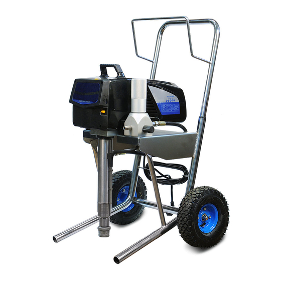
Model Number:
DP-6336iB, DP-6337iB
With Electronical Pressure Control, Brushless Motor
Please read and keep this manual, Read carefully before attempting to assemble, install, operate or maintain the
product described. Protect yourself and others by observing all safety information. Failure to comply with instructions
could result in personal injury and/or property damage! Retain instruction for future reference.
www.dpairless.com www.dino-power.com
www.airlesspaintsprayer-pump.com
1
Advertisement
Table of Contents

Summary of Contents for Dino-Power DP-6336iB
- Page 1 Instruction Model Number: DP-6336iB, DP-6337iB With Electronical Pressure Control, Brushless Motor Please read and keep this manual, Read carefully before attempting to assemble, install, operate or maintain the product described. Protect yourself and others by observing all safety information. Failure to comply with instructions could result in personal injury and/or property damage! Retain instruction for future reference.
-
Page 2: Table Of Contents
DO NOT allow body to touch a leak in the fluid hose. Table of Contents NEVER put hand in front of the gun. Gloves will not Safety Precautions ..........2 General Description ..........3 provide protection against an injection injury. Operation ..............4 ALWAYS lock gun trigger, shut pump off, and release Setup ..............4 all pressure before servicing, cleaning tip or guard,... -
Page 3: General Description
2. Avoid all ignition sources such as static electricity DANGER---Improper installation of the grounding plug sparks, electrical appliances, flames, pilot lights, hot can result in a risk of electric shock. If repair or objects, and sparks from connecting and disconnecting replacement of the cord or plug is necessary, do not power cords connect the green grounding wire to either flat blade... -
Page 4: Operation
1.Place the suction tube into a container of mineral Operation spirits. This equipment produces a fluid stream at extremely 2.Place the return hose into a metal waste container. high pressure. Read and understand the warnings in 3.Set the pressure to minimum by turning the pressure the Safety Precautions section at the front of this control knob to the”Min”... -
Page 5: Preparing To Paint
Preparing to Paint 11.Trigger the gun into the metal waste container until Before painting, it is important to make sure that the the old solvent is gone and fresh solvent is coming out fluid in the system is compatible with the paint that is of the gun. -
Page 6: Pressure Relief Procedure
11.Unlock the gun by turning the gun trigger lock to the 4.Unlock the gun by turning the gun trigger lock to the unlocked position. unlocked position. (Ground the gun by holding it against the edge of the metal 5.Hold the metal part of the gun firmly to the side of a container while flushing. -
Page 7: Practice
Angle the spray gun slightly away from the shield and toward the surface. This will prevent paint from being Avoid arcing or holding the gun at an angle. This will forced underneath. result in an uneven finish. Shrubs next to houses should be tied back and covered with a canvas cloth. -
Page 8: Cleanup
9.Turn the unit off by moving the ON/OFF switch to the OFF position. 10.Move the PRIME/SPRAY valve up to its SPRAY position. 11.Turn the unit on. Cleanup Ground the gun by holding it against the edge of Special cleanup instructions for use with flammable the metal container while flushing. -
Page 9: Replacing The Motor Assembly
CAUTION 11. Reconnect the wires (refer to the electrical Never pull on a wire to disconnect it. Pulling on a schematic in the Parts List section of this manual). wire could loosen the connector from the wire. 12.Slide the motor cover over the motor. Secure the 2.Test your repair before regular operation of the motor cover with the four motor cover screws. -
Page 10: Replacing The Transducer
NOTE: If the motor will not dislodge from the pump 9.Unplug the transducer connection from EPC board housing: location “JP3” (refer to the electrical schematic in the Remove the front cover plate. Parts List section of this manual). Using a rubber mallet, carefully tap on the front of the 10.Using an 1/8”... -
Page 11: Replacing The Filters
Tighten securely with wrench. 3.Unscrew the return hose assembly from the pump 5.Place the cam base over the valve housing block. assembly. Lubricate the cam base with grease and 4.Remove the retaining clip that holds the suction set line up the cam with the pump block. in the foot valve. - Page 12 Never use a wrench on the piston itself. This could 4.Clean out any debris and examine the valve housing cause damage to the piston and cause leakage. and seat. If the seat is damaged, reverse or replace 11. Insert the piston guide into the retainer nut. the seat.
- Page 13 Gun Filter 1.Move the gun trigger lock to the unlocked position. 2.Loosen and remove the handle from the gun body. 3.Turning clockwise, unscrew the filter from the gun body. 4.Turning counterclockwise, screw the new or cleaned filter into the gun body. 5.Make sure the handle seal is in position and thread the handle into the gun body until secure.
- Page 15 Item Description Item Description 1 --------------Fluid section (excludes items 23 ----------------------Foot valve housing 24–38) Fluid section complete (includes 24 ----------------------Seal filter and PRIME/SPRAY valve assembly) 25---------------------- Filter. 2 --------- --Piston assembly 26 ----------------------Filter housing (includes items 10–16) 27----------------------PRIME/SPRAY valve 3 --------------Retainer assembly (includes items 28—38) 4 --------------Piston guide 28 --------------------Gasket...


Need help?
Do you have a question about the DP-6336iB and is the answer not in the manual?
Questions and answers