Table of Contents
Advertisement
Quick Links
Operating Instruction
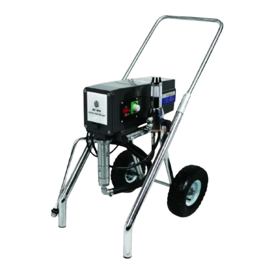
Product model:DP-6840iB airless paint sprayer
DP-6840iL
1.8 hp 3.5L
DP-6840iB
Low cart
1.8 hp 3.5L
Stand-up cart
Please read and keep this manual, Read carefully before attempting to assemble, install, operate or maintain the
product described. Protect yourself and others by observing all safety information. Failure to comply with instructions
could result in personal injury and/or property damage! Retain instruction for future reference..
www.dpairless.com www.dino-power.com
www.airlesspaintsprayer-pump.com
www.airless-paint-spray.com
Advertisement
Table of Contents

Related Manuals for Dino-Power DP-6840iB


Summary of Contents for Dino-Power DP-6840iB
- Page 1 Operating Instruction Product model:DP-6840iB airless paint sprayer DP-6840iL 1.8 hp 3.5L DP-6840iB Low cart 1.8 hp 3.5L Stand-up cart Please read and keep this manual, Read carefully before attempting to assemble, install, operate or maintain the product described. Protect yourself and others by observing all safety information. Failure to comply with instructions could result in personal injury and/or property damage! Retain instruction for future reference..
-
Page 2: Table Of Contents
Table of Contents Attention! Danger of injury by injection! In case of injury to skin caused by coating materials or Safety Precautions ..............2 solvents consult a doctor immediately. Inform the doctor of the type of coating material or cleaning agent with which the injury General Description ...............4 was caused. - Page 3 9. Attention! Please observe the following when working NOTE TO PHYSICIAN: inside and outside: Injection into the skin is a traumatic injury. It is No solvent gasses should be carried to the unit. No important to treat the injury surgically as soon as solvent gasses should form near the unit.
-
Page 4: General Description
General Description CAUTION This airless sprayer is a precision power tool used for spraying many types of materials. Read and follow this instruction Always use a minimum 12 gauge, three-wire extension manual carefully for proper operating instructions, cord with a grounded plug. Never remove the third prong maintenance, and safety information. -
Page 5: Painting
7. Move the PRIME/SPRAY valve up to the SPRAY position. 12. Lock the gun by turning the gun trigger 8. Turn the unit on and set the pressure to minimum by lock to the locked position. turning the pressure control knob to the “Min PSI” with 13. -
Page 6: Electronic Pressure Control Indicators
Spraying Technique Electronic Pressure Control Indicators The following techniques, if followed, will assure professional The following is a description of the electronic pressure control painting results. indicators. Hold the gun perpendicular to the surface and always at equal distance from the surface. Depending on the type of material, surface, or desired spray pattern, the gun should be held at a distance of 30 to 35 cm (12 to 14 inches). -
Page 7: Practice
3. Place the siphon tube into a container of the appropriate For corners and edges, split the solvent. Examples of the appropriate solvent are water for center of the spray pattern on the latex paint or mineral spirits for oil-based paints. corner or edge and spray vertically 4. -
Page 8: Maintenance
Maintenance 6. At the electronic control assembly: a. Disconnect the white wire coming from the power cord and the white wire coming from the relay. WARNING b. Disconnect the three wires coming from the potentiometer. c. Disconnect the seven wires coming from the indicator Before proceeding, follow the Pressure Relief Procedure lights assembly. -
Page 9: Replacing The Transducer
7. Loosen and remove the three motor mounting screws. NOTE: Make sure the o-ring on the transducer is in 8. Pull the motor out of the gearbox housing. place before threading the transducer into the 9. Inspect the armature gear on the end of the motor for filter housing. -
Page 10: Servicing The Fluid Section
Servicing the Fluid Section NOTE: During reassembly, make sure the black o-rings and the white back-up rings between the upper Use the following procedures to service the valves and repack housing and lower housing as well as between the fluid section. Perform the following steps before the lower housing and the foot valve housing performing any maintenance on the fluid section. -
Page 11: Replacing The Filters
15. Insert the spacer on top of the upper packing. 35. Turn on the sprayer by following the procedure in the 16. Thread the upper seal retainer into the upper housing and “Operation” section of this manual and check for leaks. torque to 25-30 ft. -
Page 12: Troubleshooting
Troubleshooting Problem Cause Solution The unit will not run. 1. The unit is not plugged in. 1. Plug the unit in. 2. Tripped breaker. 2. Reset the breaker. 3. The pressure is set too low (pressure 3. Turn the pressure control knob clockwise to control knob set at minimum setting supply power to the unit and increase the does not supply power to unit). - Page 13 Troubleshooting Problem Cause Solution Excessive surge at the spray 1. Wrong type of airless spray hose. 1. Replace hose with a minimum of 5m (50’) x gun. 10mm (1/4”) grounded textile braid airless paint spray hose. 2. Replace the spray tip following the 2.
-
Page 14: Parts Listings
Parts List Main Assembly Item DescriptionQuantity Item DescriptionQuantity Cart assembly..........1 Return hose ..........1 Drive assembly ...........1 Filter assembly..........1 Screw............4 Outlet fitting..........1 Pail hook .............1 PRIME/SPRAY valve assembly....1 Lock washer..........2 Fitting ............1 Screw............2 Fitting (high rider) ........1 Knock-off nut..........1 Fitting (low rider, not shown) ......1 Fluid section assembly .......1 Lock washer..........2 Siphon tube..........1... -
Page 15: Drive Assembly
Drive Assembly Item DescriptionQuantity Item DescriptionQuantity Electronic cover ..........1 Screw............1 Screw............3 Potentiometer mounting plate.....1 Motor assembly, 1.1 HP ......1 Nut ..............1 Front end bell assembly ......1 Cap .............1 Housing gasket ...........1 Pressure control knob.........1 Shroud gasket..........1 Potentiometer ..........1 1st stage gear assembly......1 Screw............1 2nd stage gear asembly ......1 Port plug .............1... -
Page 16: Fluid Section Assembly
Fluid Section Assembly Install upper packing with raised lip facing down. Raised Lip Closer Install lower packing with the side that has the o-ring closest to the top of the packing facing up. NOTE: When repacking the fluid section, make sure the raised lip on the bottom of the lower packing is fully outside the packing around the piston rod after insertion of... -
Page 17: Filter Assembly
Item DescriptionQuantity Item DescriptionQuantity Upper seal retainer ........1 Washer, nylon ..........1 Spacer ............1 Outlet valve seat.........1 Upper packing assembly ......1 Outlet valve retainer ........1 Upper housing ..........1 Foot valve cage ..........1 Lower packing assembly ......1 Foot valve ball ..........1 Wear ring ............1 Foot valve seat ...........1 O-ring, black ..........2 O-ring............1... -
Page 18: Prime/Spray Assembly
PRIME/SPRAY Valve Assembly NOTE: Do not exceed the sprayer's recommended maximum tip size. The following chart indicates the most common sizes and the appropriate materials to be sprayed. Tip Size Spray Material Filter Type .011 — .013 Lacquers and stains 100 mesh filter .015 —...
Need help?
Do you have a question about the DP-6840iB and is the answer not in the manual?
Questions and answers