
Related Manuals for Moxa Technologies VPort 364


Summary of Contents for Moxa Technologies VPort 364
- Page 1 Moxa VPort 364 Industrial Video Encoder User’s Manual First Edition, February 2011 www.moxa.com/product © 2011 Moxa Inc. All rights reserved. Reproduction without permission is prohibited.
- Page 2 Moxa VPort 364 Industrial Video Encoder User’s Manual The software described in this manual is furnished under a license agreement and may be used only in accordance with the terms of that agreement. Copyright Notice Copyright ©2011 Moxa Inc. All rights reserved.
-
Page 3: Table Of Contents
Overview ............................2-2 Package Checklist ..........................2-3 Product Features ..........................2-3 Typical Application ..........................2-5 Panel Layout of the VPort 364 ......................2-6 Product Description ..........................2-7 Getting Started..........................3-1 Before Getting Started ........................3-2 First-Time Installation and Configuration ....................3-2 RS-232 Console Configuration (115200, None, 8, 1, VT1 00) ............ -
Page 4: Preliminaries
Before using your VPort 364, please pay close attention to the following instructions: After opening the VPort 364 box, compare the contents of the box with the Package Checklist in Chapter 1. Notify your sales representative if any of the items are missing or damaged. -
Page 5: Introduction
Introduction The VPort 364 is a rugged networking video encoder designed for use in harsh environments. In addition to being able to handle basic video feeds, many advanced features are also included to set up surveillance or web multimedia applications. The VPort 364 is designed to provide stability, robustness, ease-of-use, and flexibility. -
Page 6: Overview
2-way audio supported for a complete surveillance solution The VPort 364 supports both audio input and audio output for voice over IP communication between a field site and central site. The 2-way audio function not only saves time, but also saves the cost of needing to add additional communication devices (such as a phone). -
Page 7: Package Checklist
To ask about SDK requirements, please contact a Moxa sales representative for details and an application form. Package Checklist The Moxa VPort 364 is shipped with the following items. If any of these items are missing or damaged, please contact your sales representative for assistance. •... - Page 8 Moxa VPort 364 Industrial Video Encoder Introduction • Dual simultaneous video streams (1 H.264 and 1 MJPEG). • Lower latency, under 200 ms. • 4 BNC video inputs • Single video stream up to 30 frames/sec in Full D1 (720 x 48resolution in NTSC, and 25 frames/ sec in Full D1 (720 x 576) resolution in PAL •...
-
Page 9: Typical Application
Moxa VPort 364 Industrial Video Encoder Introduction Typical Application... -
Page 10: Panel Layout Of The Vport 364
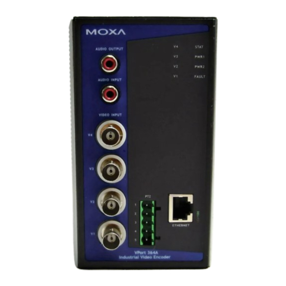
Moxa VPort 364 Industrial Video Encoder Introduction Panel Layout of the VPort 364 1. RS-232 console port 2. Hardware reset button 3. 8-pin terminal block for DI 1 to DI 4 4. 5-pin terminal block for Relay 2 and power input 2 (PWR2) 5. -
Page 11: Product Description
RCA Connectors for Audio Input/Output The VPort 364 has 2 RCA phone jacks for audio input and output on the front panel. One jack is for a MIC-in/Line-in audio input connection, which can be directly connected with a microphone or an audio source from an amplifier. - Page 12 RS-232/RS-422/RS-485 PTZ port The VPort 364 has 1 PTZ port for PTZ control. This PTZ port is an RS-232/RS-422/485 serial port with a 5 pin terminal block connector. The pin assignments are as follows:...
- Page 13 Reboot: To reboot the VPort 364, power it off and then power it back on again, or push the RESET button one time. The STAT LED will light in red as the POST (Power On Self Test) process runs. When the rebooting process is finished, the STAT LED will turn green.
-
Page 14: Getting Started
Getting Started This chapter includes information about how to install a VPort 364 video encoder. The following topics are covered in this chapter: Before Getting Started First-Time Installation and Configuration RS-232 Console Configuration (115200, None, 8, 1, VT1 00) ... -
Page 15: Before Getting Started
Select the power source The VPort 364 can be powered by a 12 to 32 VDC DC power input, or a 18 to 30 VAC AC power input. Two power inputs are provided for redundancy. Users can check the LED status located in the front panel to see if the power inputs are connected appropriately. - Page 16 Configure the VPort 364’s IP address After powering on the VPort 364, wait a few seconds for the POST (Power On Self Test) to run. The STAT LED turns green to indicate that the POST process has completed. The IP address will be assigned when the 10 or...
- Page 17 Network Environment with a DHCP Server In this case, the IP address of the VPort 364 is assigned by a DHCP Server. Use the DHCP Server’s IP address table, or use the Moxa VPort utility to determine the IP address that was assigned by the DHCP Server.
- Page 18 Network Environment without a DHCP Server: If your VPort 364 is connected to a network that does not have a DHCP server, then you will need to configure the IP address manually. The default IP address of the VPort 364 is 192.168.127.100 and the default subnet mask is 255.255.255.0.
- Page 19 Step 8: Accessing the homepage of the VPort 364’s web-based manager. After installing the ActiveX Control component, the homepage of the VPort 364’s web-based manager will appear. Check the following items to make sure the system was installed properly: 1. Video Images 2.
-
Page 20: Rs-232 Console Configuration (115200, None, 8, 1, Vt1 00)
PComm Terminal Emulator, which is free and can be downloaded from Moxa’s website. The following instructions explain how to use PComm to access the RS-232 console. 1. Use an RJ45 to DB9-F (or RJ45 to DB25-F) cable to connect the VPort 364’s RS-232 console port to a COM port on your PC. - Page 21 Moxa VPort 364 Industrial Video Encoder Getting Started 2. From the Windows desktop, click Start Programs PCommLite2.5 Terminal Emulator. 3. Select Open under Port Manager to open a new connection.
- Page 22 Moxa VPort 364 Industrial Video Encoder Getting Started 4. The Communication Parameter page of the Property window opens. Select the appropriate COM port for Console Connection, 115200 for Baud Rate, 8 for Data Bits, None for Parity, and 1 for Stop Bits.
- Page 23 Space Toggle options Previous Menu Many settings are related to video images, which cannot be shown on the RS-232 console. The VPort 364’s NOTE RS-232 console only accesses the Basic System Settings and Network Settings. For more advanced configuration, please use the web console.
-
Page 24: Mounting The Vport 364 Dimension
Moxa VPort 364 Industrial Video Encoder Getting Started Mounting the VPort 364 Dimension (Unit=mm) 3-11... -
Page 25: Din-Rail Mounting
DIN-Rail Mounting The DIN-Rail attachment plate should already be attached to the back panel of the VPort 364 when you take it out of the box. If you need to reattach the plate, make sure the metal spring is situated towards the top, as shown in the figures below. -
Page 26: Wiring Requirements
Once the screws are fixed in the wall, insert the four screw heads through the large parts of the keyhole-shaped apertures, and then slide the VPort 364 downwards, as indicated in the figure. Tighten the four screws for added stability. -
Page 27: Wiring The Redundant Power Inputs
Wiring the Redundant Power Inputs The VPort 364 has two sets of power inputs, power input 1 and power input 2, which are located on the two 5-pin terminal block connectors. Top and front views of the terminal block connectors are shown here. -
Page 28: Wiring The Digital Inputs
VPort 364’s top panel. RS-232 Connection The VPort 364 has one RS-232 (10-pin RJ45) console port, located on the top panel. Use either an RJ45-to-DB9 or RJ45-to-DB25 cable (see the cable following wiring diagrams) to connect the VPort 364’s console port to your PC’s COM port. -
Page 29: 10/100Baset(X) Ethernet Port Connection
RJ45 (10-pin) to DB25 (F) Cable Wiring 10/100BaseT(X) Ethernet Port Connection The 10/100BaseT(X) port located on the VPort 364’s front panel is used to connect to Ethernet-enabled devices. The following table shows pinouts for both MDI (NIC-type) ports and MDI-X (HUB/Switch-type) ports. We also show cable wiring diagrams for straight-through and cross-over Ethernet cables. -
Page 30: 100Basefx Ethernet Port Connection
Moxa VPort 364 Industrial Video Encoder Getting Started RJ45 (8-pin) to RJ45 (8-pin) Straight-Through Cable Wiring RJ45 (8-pin) to RJ45 (8-pin) Cross-Over Cable Wiring 100BaseFX Ethernet Port Connection The concept behind the SC port and cable is easy to understand. Since optical signals do not require a circuit to transmit data, one cable is used to transmit data and one cable is used to receive data, providing full-duplex transmission. -
Page 31: Ptz Port
PTZ Port A PTZ port is located on the VPort 364’s front panel. The port is used to connect to a PTZ motorized camera or device, so that the camera or device can be controlled from the VPort over the IP network. The PTZ port supports RS-232 or RS-422/485 signals through the terminal block. -
Page 32: Accessing The Vport 364'S Web-Based Manager
Accessing the VPort 364's Web-based Manager This chapter includes information about how to access the VPort 364 Video Encoder for the first time. The following topics are covered in this chapter: Functions Featured on the VPort’s Web Homepage VPort’s Information ... -
Page 33: Functions Featured On The Vport's Web Homepage
Audio Control The VPort 364 provides both audio input and audio output for voice over IP communication. Client users can directly enable and disable the audio input (a microphone, for example) by clicking the microphone button and... -
Page 34: Client Settings
Users can configure the following functions in Client Settings. 1. Encoder standard: Shows the encoding algorithm currently being used. VPort 364 features built-in 2 encode engines to generate dual simultaneous video streams. Each client can select the H.264 video streams from Stream 1, or the MJPEG video stream from Stream 2. -
Page 35: System Configuration
Moxa VPort 364 Industrial Video Encoder Accessing the VPort 364's Web-based Manager System Configuration A button or text link on the left side of the system configuration window only appears on the administrator’s main page. For detailed system configuration instructions, refer to Chapter 4, System Configuration. -
Page 36: Custom Commands
Relay Control The VPort 364 has 2 relay outputs for external devices, such as alarms. Administrators and permitted users can click on Open to short the Common and Normal Open digital output pins, or click on Close to short the... -
Page 37: System Configuration
System Configuration After installing the hardware, the next step is to configure the VPort 364’s settings. Users can configure by web console. The following topics are covered in this chapter: System Configuration by Web Console System Network ... -
Page 38: System Configuration By Web Console
Moxa VPort 364 Industrial Video Encoder System Configuration System Configuration by Web Console System configuration can be done remotely with Internet Explorer. To access the server, type the system configuration URL, http://<IP address of Video Server>/setup/config.html, to open the configuration main page. -
Page 39: System
Moxa VPort 364 Industrial Video Encoder System Configuration This table can also be found on the System Configuration Overview webpage. System General Settings On the General Settings page, administrators can set up the video Server name and the Date and Time, which is displayed in the image’s caption. - Page 40 Moxa VPort 364 Industrial Video Encoder System Configuration Date and Time Setting Description Default Keep current date and Use the current date and time as the VPort’s time setting. Keep current date time and time Sync with computer Synchronize VPort’s data and time setting with the local time computer time.
- Page 41 The FPS of the video stream will be reduced as more and more users access the same VPort. Currently, the NOTE VPort 364 is only allowed to send 8 unicast video streams at the same time. Therefore, limit the number of users simultaneously accessing a VPort 364 to prevent performance problems.
- Page 42 Moxa VPort 364 Industrial Video Encoder System Configuration Send to system log server Setting Description Default Send to system log Enables sending the system log to the log sever. Disable server Syslog Sever 1 The address of the first system log server.
- Page 43 Take the following steps to upgrade the firmware: Press the Browse button to select the firmware file. Step 1: For the VPort 364, the firmware file extension should be .rom. NOTE Click on the Upgrade button to upload the firmware to the VPort.
-
Page 44: Network
Moxa VPort 364 Industrial Video Encoder System Configuration Reset to Factory Default From the “Reset to Factory Default” page, click on OK (as shown in the following figure) to reset the VPort to its factory default settings. All parameters will be reset to factory defaults when you use the Factory Default function. For this reason, if you NOTE want to keep a digital copy of the current configuration, remember to export the sys_config.ini file before using... - Page 45 The VPort 364 supports standard RTSP (Real Time Streaming Protocol) streaming, which means that all devices and software that support RTSP can directly acquire and view the video images sent from the VPort 364 without any proprietary codec or SDK installations. This makes network system integration much more convenient. For different connection types, the access name is different.
- Page 46 RTSP Port: 554 is the default. Click OK to connect to the VPort 364. Wait a few seconds for QuickTime Player to establish the connection. Step 3: After the connection has been established, the VPort 364’s video will appear in the QuickTime Player Step 4: display window.
- Page 47 System Configuration NOTE The video performance of the VPort 364 may vary when using other media players. For example, you will notice a greater delay when viewing the VPort 364’s video from the QuickTime player compared to viewing it directly from the VPort 364’s built-in web server.
- Page 48 Moxa VPort 364 Industrial Video Encoder System Configuration NOTE Note that if the Sender’s email address is not set, a warning message will pop up and the e-mail system will not be allowed to operate. The 2nd SMTP Server and Sender Email are backups that are used if the 1st SMTP Server and Sender Email NOTE fail when connecting or sending email.
- Page 49 Moxa VPort 364 Industrial Video Encoder System Configuration NOTE Whenever the system reboots, a system log will be sent by email or FTP to show the login status of the VPort. The system log will be sent to the Sender email address if the SMTP server settings are correct. To send the system log via FTP, the SMTP server should be erased since the E-mail system is used by default to transmit the system log.
- Page 50 Enable or disable the UPnP function. Enable Multicast The VPort 364 supports the advanced Multicast network protocol IGMP, which can greatly improve the efficiency of network traffic. In this section, we explain multicasts, multicast filtering, and how multicast can be implemented on your VPort.
- Page 51 System Configuration The network WITH Multicast The VPort 364 is the source that delivers the multicast video stream. To benefit from the Multicast protocol, the NOTE gateway or network switch should support the multicast filtering function (such as IGMP Snooping) so that the multicast stream is delivered correctly and precisely.
- Page 52 192.168.1.128/255.255.255.128 SNMP The VPort 364 supports three SNMP protocols. The available protocols are SNMP V1, SNMP V2c, and SNMP V3. SNMP V1 and SNMP V2c use a community string match for authentication, which means that SNMP servers access all objects with read-only or read/write permissions using the community string public/private (default value).
- Page 53 Moxa VPort 364 Industrial Video Encoder System Configuration Protocol Security Authentication Data Method Version Mode Type Encryption SNMP V1, V2c V1, V2c Read Community string Use a community string match for Community authentication V1, V2c Community string Use a community string match for...
- Page 54 Moxa VPort 364 Industrial Video Encoder System Configuration V1, V2c Read Community Setting Description Default V1, V2c Read Use a community string match for authentication, which means public Community that the SNMP agent accesses all objects with read-only (max. 30 permissions using the community string public.
- Page 55 Moxa VPort 364 Industrial Video Encoder System Configuration Private MIB information The private SNMP Object ID of the VPort is the enterprise value: 8691.8.1.11. This number cannot be changed. NOTE The MIB file is MOXA-VPORT364-MIB.mib (or.my). You can find it on the software CD or the download center of the Moxa website.
-
Page 56: Dynastream Tm
Moxa VPort 364 Industrial Video Encoder System Configuration Setting Description Factory Default Host Name User-defined name for identification Blank Server 1, 2, 3, 4 The server’s URL address with complete CGI commands Ex. Blank http:// http event server:Port/CGI_Name User name... - Page 57 Moxa VPort 364 Industrial Video Encoder System Configuration Basic The administrator can adjust the number of frames per second for each channel. There are two types of frame rate status: Live and Alarm. Live status refers to the normal frames rates for live video displays. Alarm status refers to what the frame rate will be adjusted to when the DynaStream function is activated.
-
Page 58: Video
Moxa VPort 364 Industrial Video Encoder System Configuration Setting Description Factory Default Enable To enable or disable the DynaStream function. Disabled Duration This refers to the time period that DynaStream is in operation. 5 seconds For example, if the duration is set to 5 seconds, then the frame rate will change from the Live to the Alarm status for the duration of 5 seconds. - Page 59 Moxa VPort 364 Industrial Video Encoder System Configuration Channel Selection Description Default Channel 1, 2, 3, or 4 For configuring the channels’ image settings. Channel 1 Image Information Setting Description Default Description (max. of 14 The customized description shown on the...
- Page 60 Changing the modulation requires resetting the server to detect the camera. Please ensure that your configurations are saved before resetting the server. Video Performance The VPort 364 can send dual video streams simultaneously: one H.264 and one MJEPG. Each video stream can be used for a different specific application. Stream Select...
- Page 61 IP system, and when specifying the requirements for the video system. Camera Control Four cameras can be connected to the VPort 364. To setup the PTZ control, administrators need to configure the parameters of each video channel. 5-25...
- Page 62 Moxa VPort 364 Industrial Video Encoder System Configuration The VPort supports PTZ (PAN/TILT/ZOOM) motorized camera control via an RS-232, RS-422, or RS-485 PTZ/ COM port. Before setting up camera control, the administrator should first connect the PTZ camera to the VPort.
-
Page 63: Serial Port
System Configuration Serial Port The VPort 364 has a PTZ port that can be set for RS-232, RS-422, or RS-485 serial interface. Refer to the Quick Installation Guide or Chapter 2 for the connector type and pin assignment. PTZ port This PTZ port is used to control a PTZ camera. - Page 64 Moxa VPort 364 Industrial Video Encoder System Configuration In Transparent PTZ Control mode, the serial data from the legacy PTZ control panel or joystick will be transformed into IP packets for transmission over a TCP/IP network, and once the VPort video encoder receives these IP packets, the PTZ control commands will be transformed back to serial data format for controlling the PTZ camera’s action.
- Page 65 Moxa VPort 364 Industrial Video Encoder System Configuration PTZ Camera Drivers VPort products come with PTZ camera drivers for some of the popular PTZ cameras. Administrators can select the correct PTZ driver in the “Select the Camera Driver” menu. If the attached PTZ camera is not supported by the VPort, administrators can use the Custom Camera function to enter the proprietary commands for pan, tilt, zoom, and focus control.
-
Page 66: Audio
Moxa VPort 364 Industrial Video Encoder System Configuration The control protocols are available from the PTZ camera’s supplier. You will need to get the protocols from the NOTE supplier before programming the PTZ camera. Uploading a PTZ Camera Driver In addition to the PTZ camera drivers and custom camera functions supported by the VPort, an alternative user-friendly Upload a PTZ Camera Driver function is available for implementing the PTZ camera control. -
Page 67: Alarm
Moxa VPort 364 Industrial Video Encoder System Configuration Alarm System Alarm In addition to the LED indicators, three kinds of system alarms are provided by the VPort 364 for notifying the system operations administrator. Alarm Type Triggered Condition Triggered Action... - Page 68 Moxa VPort 364 Industrial Video Encoder System Configuration Event Alarm Four kinds of event alarm are provided by the VPort for building an intelligent video surveillance system. Alarm Type Triggered Condition Triggered Action Video Motion Detection (VMD) VMD 1 Relay...
- Page 69 Moxa VPort 364 Industrial Video Encoder System Configuration NOTE The delay before triggering the next alarm cannot be less than the time needed to take a snapshot after an event (post-event image). Send Alarm with Snapshot images Setting Description Default...
- Page 70 Moxa VPort 364 Industrial Video Encoder System Configuration Event Type Setting Description Default Video Loss, Digital Set up the schedule of each kind of event type. Video Loss Input, CGI Event, and Sequential Snapshot Weekly Schedule Setting Description Default Event Alarms are active Select the option “Event Alarms are active all the time”...
- Page 71 Moxa VPort 364 Industrial Video Encoder System Configuration Setting Description Default Enable VMD alarm Enable or disable the Video Motion Detection alarm Disabled Show alert on the Enable or disable the “show the alert,” which when enabled Disabled image when VMD is...
- Page 72 Moxa VPort 364 Industrial Video Encoder System Configuration NOTE Once the Show alert on the image when VMD is triggered is enabled, the red frames that appear on the homepage image indicate the size of the VMD window set up by the administrator.
- Page 73 Moxa VPort 364 Industrial Video Encoder System Configuration Trigger Conditions and Actions Administrators can set triggers, such as Trigger Relay1 alarm, Trigger Relay2 alarm, Send snapshot image via E-mail, Send snapshot image via FTP, and Send Message via HTTP Event servers for each VMD.
- Page 74 Moxa VPort 364 Industrial Video Encoder System Configuration Setting Description Default Enable digital input Enable or disable the digital input alarm. Disable alarm Trigger Conditions Setting Description Default High The DI is always in the “High” state after an alarm is detected. Disable The DI is always in the “Low”...
- Page 75 Moxa VPort 364 Industrial Video Encoder System Configuration Video Loss The Video Loss event means that the VPort cannot detect the analog video signal. Video Loss Trigger Actions Setting Description Default Enable video loss alarm Enable or disable video loss alarm.
- Page 76 Moxa VPort 364 Industrial Video Encoder System Configuration CGI Event The VPort can accept 5 CGI commands, which are sent from external devices, such as ioLogik series Ethernet I/O, to be the event alarms. The VPort only can accept the CGI commands that follow the VPort’s CGI commands format.
- Page 77 Moxa VPort 364 Industrial Video Encoder System Configuration Snapshot image Setting Description Default Channel 1, 2, 3 or 4 Select the video channel for sending the snapshot image once a Disabled CGI event is triggered. Sequential Snapshot With this feature, the VPort can upload snapshots periodically to an external E-mail or FTP server as a live video source.
-
Page 78: Frequently Asked Questions
Basically, there is no limitation. However the video quality also depends on the network. To achieve the best effect, the VPort 364 video encoder will allow 8 video streams for udp/tcp/http connections, and 4 multicast video streams. We recommend using an additional web server that retrieves images from the video encoder periodically if you need to host a large number of users. - Page 79 Moxa VPort 364 Industrial Video Encoder Frequently Asked Questions 3. Number of users. 4. More complicated objects result in larger image files. 5. The speed of the PC or notebook that is responsible for displaying images. FAQ 7: How can I keep the video encoder as private as possible? The video encoder is designed for surveillance purposes and has many flexible interfaces.
-
Page 80: Modbus Address Table
Word 2 Hi byte = ‘\0’ Word 2 Lo byte = ‘\0’ 0x0030 20 word Product Name = "VPort 364" Word 0 Hi byte = ‘V’ Word 0 Lo byte = ‘P’ Word 1 Hi byte = ‘0’ Word 1 Lo byte = ‘r’... - Page 81 Moxa VPort 364 Industrial Video Encoder ModBus Address Table 0x0058 88 1 word Power 1 0x0000:Off 0x0001:On 0x0059 1 word Power 2 0x0000:Off 0x0001:On 0x005A 1 word Fault LED Status 0x0000:No 0x0001:Yes 0x005B 1 word Channel 1 Video Signal 0x0000:Off...
- Page 82 Moxa VPort 364 Industrial Video Encoder ModBus Address Table 0x805 1 word CH3 DynaStream alwaysrun/forcestop 1: Always Run 0: Force Stop 0x806 1 word CH4 DynaStream Duration 1~999 0x807 1 word CH4 DynaStream alwaysrun/forcestop 1: Always Run 0: Force Stop...
-
Page 83: Settings Of Supported Ptz Cameras
Settings of Supported PTZ Cameras Since the COM port settings can be adjusted to other than the default settings, check the correct default settings for the attached camera. Camera model Baud rate Data bits Stop bit Parity bit Pelco P, D protocol 2400 None DynaDome/DynaDome... -
Page 84: Time Zone Table
Time Zone Table The hour offsets for different time zones are shown below. You will need this information when setting the time zone in automatic date/time synchronization. GMT stands for Greenwich Mean Time, which is the global time that all time zones are measured from. (GMT-12:00) International Date Line West (GMT-11:00) - Page 85 Moxa VPort 364 Industrial Video Encoder Time Zone Table (GMT+03:00) Nairobi (GMT+03:30) Tehran (GMT+04:00) Abu Dhabi, Muscat (GMT+04:00) Baku, Tbilisi, Yerevan (GMT+04:30) Kabul (GMT+05:00) Ekaterinburg (GMT+05:00) Islamabad, Karachi, Tashkent (GMT+05:30) Chennai, Kolkata, Mumbai, New Delhi (GMT+05:45) Kathmandu (GMT+06:00) Almaty, Novosibirsk (GMT+06:00) Astana, Dhaka...
-
Page 86: Technical Specifications
Technical Specifications Video Video Compression: H.264 (MPEG4 part 10, AVC) or MJPEG Video Inputs: 4, BNC connector (1.0 Vpp, 75 ohm) Video Streams: Dual streams (one for H.264, the other for MJPEG) NTSC/PAL: Manual Video Resolution and FPS (frames per second) in single video stream: Video Viewing: •... - Page 87 Moxa VPort 364 Industrial Video Encoder Technical Specifications Physical Characteristics Housing: Metal, IP30 protection Dimensions: 80.2 x 135 x 105 mm (3.16 x 5.31 x 4.13 in) Weight: 1110 g Installation: DIN-Rail mounting or panel mounting (with optional mounting kit)
- Page 88 Moxa VPort 364 Industrial Video Encoder Technical Specifications System Requirements CPU: Pentium 4, 2.4 GHz or above Memory: 512 MB memory or above OS: Windows XP/2000 with SP2 or above Browser: Internet Explorer 6.x or above Multimedia: DirectX 9.0c or above...
Need help?
Do you have a question about the VPort 364 and is the answer not in the manual?
Questions and answers