Moxa Technologies VPort 351 Series Quick Installation Manual
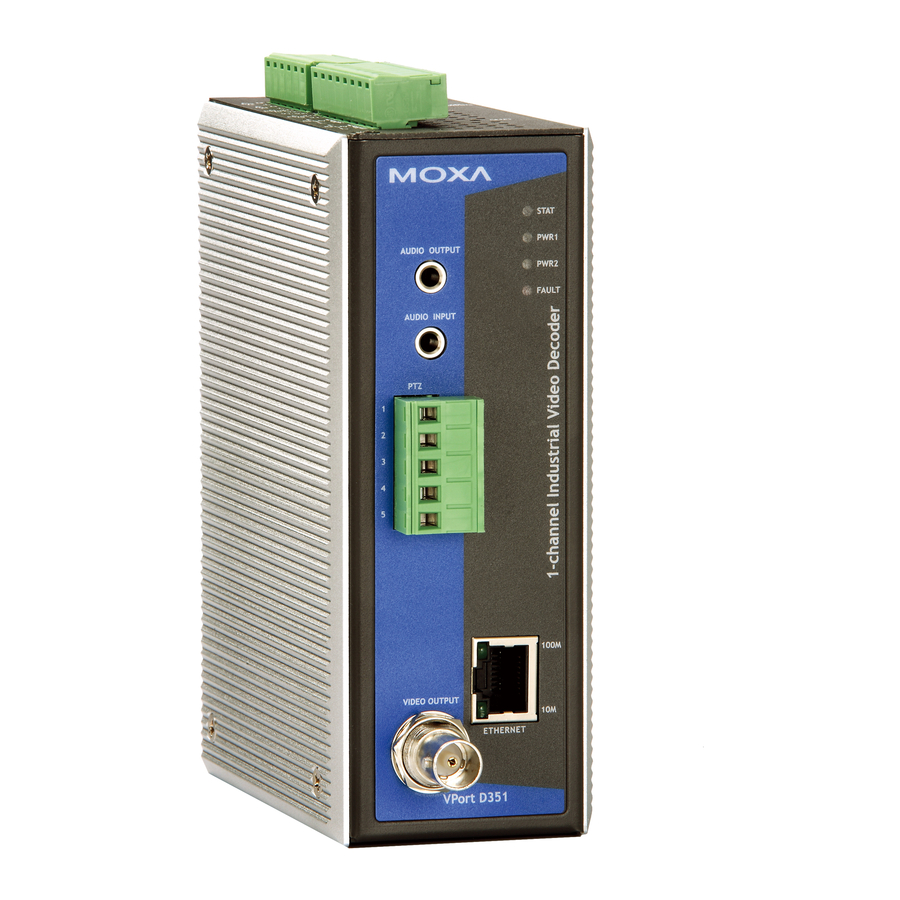
Industrial video encoder
Hide thumbs
Also See for VPort 351 Series:
- User manual (80 pages) ,
- Quick installation manual (23 pages)
Table of Contents
Advertisement
Quick Links
Advertisement
Table of Contents

Related Manuals for Moxa Technologies VPort 351 Series


Summary of Contents for Moxa Technologies VPort 351 Series
- Page 2 MOXA Industrial Video Encoder VPort 351 Series Quick Installation Guide Third Edition, May 2007 Moxa Networking Co., Ltd. Tel: +886-2-8919-1230 Fax: +886-2-8919-1231 www.moxa.com support@moxa.com (Worldwide) support@usa.moxa.com (The Americas) P/N: 1802003510112...
-
Page 3: Package Checklist
Overview The VPort 351 is a high performance, 1-channel industrial video encoder that provides up to full D1 (720 x 480) @ 30 FPS video performance. The VPort 351 is designed to support multi-codecs, including MJPEG and MPEG4 algorithms. In addition, a continuous video pre/post event-trigger video record function is supported to enhance video surveillance systems. - Page 4 TCP, UDP, and HTTP network transmission modes Allows simultaneous access of up to 10 clients Set video quality to CBR (constant bit rate) or VBR (variable bit rate) Full D1, 4CIF, VGA, QVGA, and CIF video resolution supported Timestamp and text overlay supported RS-232/RS-422/RS-485 COM port for controlling PTZ (PAN/TILT/ZOOM) motorized camera UPnP and IP filtering supported...
- Page 5 VPort 351 Panel Layout VPort 351 VPort 351-M-SC Front Panel View Front Panel View 1. Grounding screw Top Panel View 2. RS-232 console port 3. Hardware reset button 4. 6-pin terminal block for DI 1, DI 2, power input 2 (PWR2) RS-232 5.
-
Page 6: First-Time Installation And Configuration
First-Time Installation and Configuration Before installing the VPort 351 video encoder, check to make sure that all items in the Package Checklist are in the box. In addition, you will need to use a notebook or PC equipped with an Ethernet port. Step 1: Select the Power Source The VPort 351 can be powered by a DC power input from 12 to 32 VDC, or an AC power input from 18 to 30 VAC. - Page 7 NOTE The PTZ control protocol is not standardized. To use a particular PTZ control protocol, the video server must support the driver for that protocol. Currently, the VPort 351 supports PTZ control protocol drivers for: 1. Pelco D 2. DynaColor SmartDome (supported by V2.0 firmware) If you need to use a protocol that is not on the list, you will need to contact the manufacturer of the camera to get the PTZ control commands, and then program its PTZ control in the VPort 351’s...
- Page 8 2. When the search has finished, the Model Name, IP address, MAC address, Serial (i.e., serial number), and HTTP Port of the VPort will be listed in the VPort Utility window. NOTE Serial refers to the production serial number of this VPort, and the HTTP Port number is the http port used by this VPort.
-
Page 9: Video Information
NOTE For Windows XP SP2 or above operating systems, the ActiveX Control component will be blocked for system security reasons. In this case, the VPort’s security warning message window may not appear. Users should unblock the ActiveX control function or disable the security configuration to enable the installation of VPort’s ActiveX Control component. - Page 10 Step 9: Accessing VPort’s System Configuration Click on System Configuration to access the overview of the system configuration to change the configuration. Model Name, Server Name, IP Address, MAC Address, Firmware Version, and LED Status appear in the green bar near the top of the page. Use this information to check the system information and installation.
-
Page 11: Mounting Dimensions
Mounting Dimensions 15.10 30.00 40.00 13.10 25.40 9.00 DlN-Rail DlN-Rail Kit Front View 105.00 Side View 13 18 13 7.75 7.75 30.50 DlN-Rail Kit 13.9 18.2 13.9 Rear View Wall Mounting Kit DIN-Rail Mounting The aluminum DIN-Rail attachment plate should already be attached to the back panel of the VPort 351 when you take it out of the box. -
Page 12: Wall Mounting (Optional)
Wall Mounting (Optional) Follow the steps below to mount the VPort 351 on a wall or panel. STEP 1: Remove the aluminum DIN-Rail attachment plate from the VPort 351, and then attach the wall mount plates, as shown in the diagrams below. plate ⇒... -
Page 13: Grounding The Vport 351
You should also pay attention to the following: Use separate paths to route wiring for power and devices. If power wiring and device wiring paths must cross, make sure the wires are perpendicular at the intersection point. NOTE: Do not run signal or communications wiring and power wiring in the same wire conduit. -
Page 14: Wiring The Relay Output
Wiring the Relay Output The VPor 351 has two sets of relay outputs, labeled RELAY 1 and RELAY 2, located on the 8-pin terminal block connector. Each relay Normal Open output uses 3 of the contacts on the Common Normal Close 8-pin terminal block. -
Page 15: 10/100Baset(X) Ethernet Port Connection
You may then use a console terminal program, such as MOXA PComm Terminal Emulator, to access VPort 351’s console configuration utility. RJ45 (10-pin) Console Port Pinouts Description ------ ------ ------ ------ RJ45 (10-pin) to DB9 (F) Cable Wiring Moxa COM Port EtherDevice Server RJ45 Plug Pin 1... -
Page 16: 100Basefx Ethernet Port Connection
MDI Port Pinouts MDI-X Port Pinouts 8-pin RJ45 Signal Signal RJ45 (8-pin) to RJ45 (8-pin) Straight-Through Cable Wiring Straight-Through Cable VPort Ethernet Switch Port Port RJ45 Plug Pin 1 RJ45 RJ45 Connector Cable Wiring Connector RJ45 (8-pin) to RJ45 (8-pin) Cross-Over Cable Wiring Cross-Over Cable VPort Ethernet NIC Port... -
Page 17: Led Indicators
Pin Assignment PIN RS-422/485 RS-232 T-\D- T+\D+ LED Indicators Several LED indicators are located on the front panel of the VPort 351. The function of each LED is described in the table below. Color State Description Hardware initialization FLASH Software initialization STAT System boot-up GREEN... -
Page 18: Hardware Reset
RS-232 or RS-485 signals are being transmitted GREEN RS-232 or RS-485 signals are not being transmitted or have not been detected Hardware Reset A recessed RESET button is provided for restoring the system to the factory default settings. When the system fails to install properly, or operates abnormally, push the RESET button located on the top panel of the VPort 351 to restore the factory defaults. -
Page 19: Serial Port
Serial Port PTZ port 1 RS-232 or RS-422/485 Terminal Block connector; Max. speed of 115.2 Kbps Console port 1 RS-232 RJ45 port GPIO Digital Inputs 2, max. 8 mA “High”: +13V to +30V “Low”: -30V to +3V Relay Outputs 2 (max. 24 VDC @ 1A) LED Indicators STAT Indicates if the system booted properly... -
Page 20: Moxa Internet Services
MTBF 160,000 hours WARRANTY 5 years Alarm Features Pre/Post alarm video recording (9 MB memory) Video motion detection with sensitivity tuning Daily repeat timing schedule JPEG snapshots for pre/trigger/post alarm images Automatic transfer of stored images by email or FTP with event-triggered actions PAN/TILT/ZOOM PTZ camera control through RS-232/422/485... - Page 21 Soporte en Ingeniería y Equipos, S.A de C.V ¡SOLUCIONES! Para el ahorro y control de la energía eléctrica AGUASCALIENTES (MATRIZ) Priv. Cerro de la bufa No. 105 Fracc. Lomas del Campestre Aguascalientes, Ags. C.P. 20129 Tel: (449) 145 6701 Fax:(449) 145 6703 GUADALAJARA Siempre Viva No.
Need help?
Do you have a question about the VPort 351 Series and is the answer not in the manual?
Questions and answers