
Subscribe to Our Youtube Channel
Related Manuals for Moxa Technologies VPort 451


Summary of Contents for Moxa Technologies VPort 451
- Page 1 Moxa VPort 451 Industrial Video Encoder User’s Manual First Edition, March 2010 © 2010 Moxa Inc. All rights reserved. Reproduction without permission is prohibited.
-
Page 2: Technical Support Contact Information
Moxa VPort 451 Industrial Video Encoder User’s Manual The software described in this manual is furnished under a license agreement and may be used only in accordance with the terms of that agreement. Copyright Notice Copyright © 2010 Moxa Inc. - Page 3 Before using your VPort 451, please pay close attention to the following instructions: After opening the VPort 451 box, compare the contents of the box with the Package Checklist in Chapter 1. Notify your sales representative if any of the items are missing or damaged.
-
Page 4: Table Of Contents
Introduction ....................1-1 Overview..........................1-2 Package Checklist ........................1-4 Product Features ........................1-5 Typical Application........................1-6 Panel Layout of the VPort 451....................1-7 Product Description ......................... 1-8 Chapter 2 Getting Started .....................2-1 Before Getting Started ......................2-2 First-Time Installation and Configuration................2-2 RS-232 Console Configuration (38400, None, 8, 1, VT1 00) ........ - Page 5 Alarm.......................... 4-45 Appendix A Frequently Asked Questions ..............A-1 Appendix B Settings of Supported PTZ Cameras............B-1 Appendix C Time Zone Table..................C-1 Appendix D Technical Specifications ................D-1...
-
Page 6: Chapter 1 Introduction
Introduction Chapter 1 The VPort 451 is a rugged networking video encoder designed for use in harsh environments. addition to being able to handle basic video feeds, many advanced features are also included to set up surveillance or web multimedia applications. The VPort 451 is designed to provide stability, robustness, ease-of-use, and flexibility. -
Page 7: Overview
Three video streams for meeting versatile application requirements VPort 451 is a powerful video encoder. Aside from the high quality MPEG4 video compression, it can also generate a maximum of three video streams: two MPEG4 and one MJPEG simultaneously, to meet the needs of specific applications. - Page 8 (such as a phone). Rugged design for industrial environments The VPort 451 is an industrial video encoder, which means that it is designed for harsh industrial environments. With the 12/24 VDC and 24 VAC redundant power inputs, IP30 protection, and DIN-Rail mounting, the VPort 451 meets the critical requirements of most industrial applications.
-
Page 9: Package Checklist
To ask about SDK requirements, please contact a Moxa sales representative for details and an application form. Package Checklist The Moxa VPort 451 is shipped with the following items. If any of these items are missing or damaged, please contact your sales representative for assistance. VPort 451... -
Page 10: Product Features
VPort 451 User’s Manual Introduction Product Features High Performance Video/Audio Networking Solution Works with NTSC/PAL analog video cameras Supports MPEG4/MJPEG video compression technologies Up to 3 simultaneous video streams (2 MPEG4 and 1 MJPEG). Lower latency, under 200 ms. 1 BNC video inputs... -
Page 11: Typical Application
VPort 451 User’s Manual Introduction Intelligent Alarm Trigger Built-in Video Motion Detection (VMD) Equipped with 2 DIs and 2 relays (DO) for external sensors and alarms Snapshot images provided for pre, trigger, and post alarm Sequential snapshot images supported Messages with snapshot images can be sent via FTP or Email... -
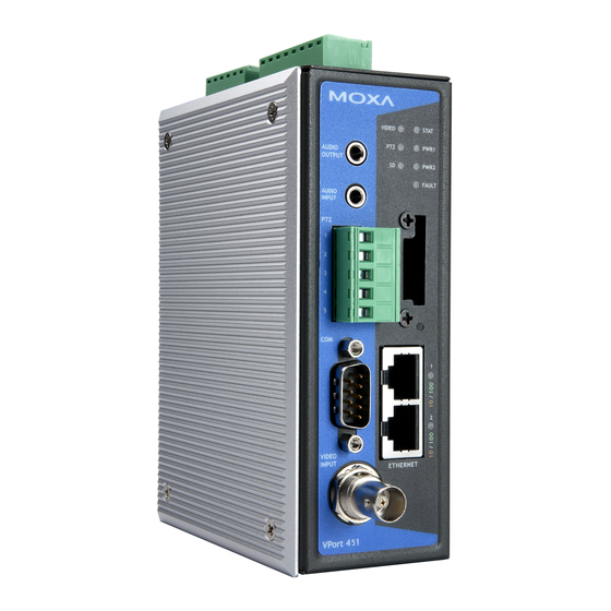
Page 12: Panel Layout Of The Vport 451
VPort 451 User’s Manual Introduction Panel Layout of the VPort 451 Top Panel View Grounding screw RS-232 console port RS-232 CONSOLE Hardware reset button 8-pin terminal block for Relay 1, Relay 2, and power input 1 (PWR1) 6-pin terminal block for DI 1, DI 2, power input 2... -
Page 13: Product Description
3.5 mm phone jacks for audio input/output The VPort 451 has two 3.5 mm phone jacks for audio input and output on the front panel. One jack is for a MIC-in/Line-in audio input connection, which can be directly connected with a microphone or an audio source from an amplifier. - Page 14 Two 10/100 Mbps Ethernet ports or one 100 Mbps fiber optic Ethernet port The VPort 451 series of video encoders come in three models: the VPort 451 has 2 RJ45 10/100M Ethernet ports (LEDs on the left corners of the ports indicate 10M or 100M), the VPort 451-S-SC has one single mode fiber optic Ethernet ports, and the VPort 451-M-SC has one multi mode fiber optic Ethernet ports.
- Page 15 PTZ driver. RS-232/RS-422/RS-485 COM port The VPort 451 has 1 COM port for connecting a PTZ motorized camera or serial device. The COM port transmits RS-232 or RS-422/485 signals over the TCP/IP network. Users can use this COM port (DB9 male connector) to monitor data or control a serial device, or for the control of a PTZ motorized camera.
- Page 16 The front panel of Moxa’s VPort 451 has an SD card slot that supports the SDHC interface. An SD card can be used for recording video if the network is down. Currently, the maximum SD capacity is 32GB, which is supported by the VPort 451. To plug in a SD card follow these simple steps.
-
Page 17: Reset Button
1. Reboot: To reboot the VPort 451, power it off and then power it back on again, or push the RESET button one time. The STAT LED will light in red as the POST (Power On Self Test) process runs. When the rebooting process is finished, the STAT LED will turn green. -
Page 18: Chapter 2 Getting Started
Getting Started Chapter 2 This chapter includes information about how to install a VPort 451 video encoder. The following topics are covered: Before Getting Started First-Time Installation and Configuration RS-232 Console Configuration (38400, None, 8, 1, VT1 00) Mounting the... -
Page 19: Before Getting Started
Step 1: Select the power source The VPort 451 can be powered by a 12 to 32 VDC DC power input, or a 18 to 30 VAC AC power input. Two power inputs are provided for redundancy. Users can check the LED status located in the front panel to see if the power inputs are connected appropriately. - Page 20 In addition, the COM PORT with the DB9 male connector can also be used to connect general serial devices, such as card readers, for transmitting serial data over a TCP/IP network. This port can be used to connect serial devices to the VPort 451 (however, the port cannot be used to connect video cameras).
- Page 21 Step 5: Configure the VPort 451’s IP address After powering on the VPort 451, wait a few seconds for the POST (Power On Self Test) to run. The STAT LED turns green to indicate that the POST process has completed. The IP address will be assigned when the 10 or 100 Mbps NETWORK LED blinks.
- Page 22 VPort 451 User’s Manual Getting Started Using the Moxa Ethernet Switch And Video Server Configuration Utility (edscfgui.exe), as described below: 1. Run the edscfgui.exe program to search for the VPort and EDS switches. After the Utility window opens, you may also select or click on Broadcast Search, which is located under the...
- Page 23 VPort 451 User’s Manual Getting Started 3. When the search has ended, the Model Name, MAC address, and IP address of the EDS Switch and the VPort will be listed in the Utility window. NOTE Broadcast Search can only be used to search for devices on the same LAN domain. If your devices are located on a different LAN domain, use Specify IP Address to search for the device by inputting the IP address.
- Page 24 Network Environment without a DHCP Server: If your VPort 451 is connected to a network that does not have a DHCP server, then you will need to configure the IP address manually. The default IP address of the VPort 451 is 192.168.127.100 and the default subnet mask is 255.255.255.0.
- Page 25 Getting Started Step 8: Accessing the homepage of the VPort 451’s web-based manager. After installing the ActiveX Control component, the homepage of the VPort 451’s web-based manager will appear. Check the following items to make sure the system was installed properly: 1.
-
Page 26: Console Configuration (38400, None, 8, 1, Vt1 00)
You cannot connect to the VPort 451 simultaneously by serial console and Telnet. 2. You may connect to the VPort 451 simultaneously by web browser and serial console, or by web browser and Telnet. However, we strongly recommend that you use only one connection method at a time. - Page 27 VPort 451 User’s Manual Getting Started 3. Select Open under Port Manager to open a new connection. 4. The Communication Parameter page of the Property window opens. Select the appropriate COM port for Console Connection, 38400 for Baud Rate, 8 for Data Bits, None for Parity, and 1 for Stop Bits.
- Page 28 VPort 451 User’s Manual Getting Started 6. A blank screen will appear. Press Enter, after which a login message will appear. Only the administrator is allowed to use this console configuration. Use admin as the username and the associated admin password as the password. Press Enter to continue.
-
Page 29: Mounting The Vport 451 Dimension
NOTE Many settings are related to video images, which cannot be shown on the RS-232 console. The VPort 451’s RS-232 console only accesses the Basic System Settings and Network Settings. For more advanced configuration, please use the web console. Mounting the VPort 451 Dimension 8.7 mm... -
Page 30: Din-Rail Mounting
Getting Started DIN-Rail Mounting The DIN-Rail attachment plate should already be attached to the back panel of the VPort 451 when you take it out of the box. If you need to reattach the plate, make sure the metal spring is situated towards the top, as shown in the figures below. -
Page 31: Wiring Requirements
Wiring Requirements ATTENTION Be sure to disconnect the power cord before installing and/or wiring your Moxa VPort 451. Calculate the maximum possible current in each power wire and common wire. Observe all electrical codes dictating the maximum current allowable for each wire size. -
Page 32: Grounding The Vport 451
Wiring the Redundant Power Inputs The VPort 451 has two sets of power inputs, power input 1 and power input 2, which are located on the 6-pin and 8-pin terminal block connectors. Top and front views of the terminal block connectors are shown here. -
Page 33: Wiring The Relay Output
Wiring the Relay Output The VPort 451 has two sets of relay output, relay 1 and relay 2, which are located on the 8-pin terminal block connector. Each relay output consists of the 3 contacts of the terminal block on the VPort 451’s top panel. -
Page 34: Rs-232 Connection
Getting Started RS-232 Connection The VPort 451 has one RS-232 (10-pin RJ45) console port, located on the top panel. Use either an RJ45-to-DB9 or RJ45-to-DB25 cable (see the cable following wiring diagrams) to connect the VPort 451’s console port to your PC’s COM port. You may then use a console terminal program, such as the Moxa PComm Terminal Emulator, to access the VPort 451’s console configuration... -
Page 35: 10/100Baset(X) Ethernet Port Connection
VPort 451 User’s Manual Getting Started 10/100BaseT(X) Ethernet Port Connection The 10/100BaseT(X) port located on the VPort 451’s front panel is used to connect to Ethernet-enabled devices. The following table shows pinouts for both MDI (NIC-type) ports and MDI-X (HUB/Switch-type) ports. -
Page 36: 100Basefx Ethernet Port Connection
SC-Port to SC-Port Cable Wiring NOTE The 2 Ethernet ports on the VPort 451’s front panel can be used as cascade links or to provide port redundancy. When used as cascade links, you will need to calculate the number of video streams in order to optimize the transmission bandwidth. -
Page 37: Com Port
Data-(A) PTZ Port A PTZ port is located on the VPort 451’s front panel. The port is used to connect to a PTZ motorized camera or device, so that the camera or device can be controlled from the VPort over the IP network. -
Page 38: Sd Card Slot
SD card. If the SD LED indicator flashes red, it means the unmounting of the SD card failed. At this point, you can remove the SD card, but you will need to reboot the VPort 451 to enable the SD card slot function for future SD cards. -
Page 39: Accessing The Vport 451'S Web-Based Manager
Accessing the VPort 451’s Web-based Chapter 3 Manager This chapter includes information about how to access the VPort 451 Video Encoder for the first time. The following topics are covered: Functions Featured on the VPort’s Web Homepage VPort’s Information Server Name... -
Page 40: Functions Featured On The Vport's Web Homepage
VPort 451 User’s Manual Accessing the VPort 461’s Web-based Manager Functions Featured on the VPort’s Web Homepage The homepage of the VPort’s web console shows information specific to that VPort, the camera image, and configurations for the client and server. -
Page 41: Camera Image View
Audio Control The VPort 451 provides both audio input and audio output for voice over IP communication. Client users can directly enable and disable the audio input (a microphone, for example) by clicking the microphone button and the audio output (a speaker, for example) by clicking the speaker button from the VPort’s web homepage. -
Page 42: System Configuration
VPort 451 User’s Manual Accessing the VPort 461’s Web-based Manager protocol. The selected protocol will be stored on the user’s PC, and will be used for the next connection. NOTE For multicast video stream settings, please refer to System Configuration Network Multicast. -
Page 43: Show Ptz Control Panel
VPort 451 User’s Manual Accessing the VPort 461’s Web-based Manager Show PTZ Control Panel Users can click this link to pop up a new window for PTZ Control. To select a camera, click the target camera’s image view. PAN, TILT... -
Page 44: Custom Ptz Camera Commands
To save the image, right-click and select the Save option. Relay Control The VPort 451 has 2 relay outputs for external devices, such as alarms. Administrators and permitted users can click on Open to short the Common and Normal Open digital output pins, or... -
Page 45: Chapter 4 System Configuration
System Configuration Chapter 4 After installing the hardware, the next step is to configure the VPort 451’s settings. Users can configure by web console. This chapter includes the following sections: System Configuration by Web Console System Network Video Serial Port... -
Page 46: System Configuration By Web Console
VPort 451 User’s Manual System Configuration System Configuration by Web Console System configuration can be done remotely with Internet Explorer. To access the server, type the system configuration URL, http://<IP address of Video Server>/setup/config.html, to open the configuration main page. - Page 47 VPort 451 User’s Manual System Configuration Configure the Size (Resolution), FPS, and Video Quality Video Performance Camera Control Set up the Camera’s PTZ Control Configure the PTZ Port interface, control mode, and serial PTZ port parameters. Serial port Configure the COM (DB9) Port interface, operation mode, COM port and serial parameters.
-
Page 48: System
VPort 451 User’s Manual System Configuration System General Settings On the General Settings page, administrators can set up the video Server name and the Date and Time, which is displayed in the image’s caption. Server name Setting Description Default Use a different server name for each server to help identify the different Max. - Page 49 VPort 451 User’s Manual System Configuration NOTE Select the Automatic option to force the VPort to synchronize automatically with timeservers over the Internet. However, synchronization may fail if the assigned NTP server cannot be reached, or the VPort is connected to a local network. Leaving the NTP server blank will force the VPort to connect to default timeservers.
- Page 50 The FPS of the video stream will be reduced as more and more users access the same VPort. Currently, the VPort 451 is only allowed to send 8 unicast video streams and 4 multicast video streams at the same time. Therefore, limit the number of users simultaneously accessing a VPort 451 to prevent performance problems.
- Page 51 VPort 451 User’s Manual System Configuration Local Video Recording Setting Setting Description Default Enable video Enable the video recording action once the recording after Enable network is down network link is down FTP Daemon Setting Description Default Enable the FTP service for downloading the...
- Page 52 VPort 451 User’s Manual System Configuration System Diagnosis VPort products have a self-diagnosis function to let the administrator get a quick view of the system and connection status. Administrators can save this diagnosis information in a file (diagnosis.log) by clicking the Export to a File button, or send the file via email by clicking the...
- Page 53 VPort 451 User’s Manual System Configuration System Log History The system log contains useful information, including current system configuration and activity history with timestamps for tracking. Administrators can save this information in a file (system.log) by clicking the Export to a File button, or send the file by email by clicking the Send a Report via Email button.
-
Page 54: System Parameters
VPort 451 User’s Manual System Configuration System Parameters The System Parameters page allows you to view all system parameters, which are listed by category. The content is the same as the VPort’s sys_config.ini file. Administrators can also save this information in a file (sys_config.ini) by clicking the Export to a File button, or import a file by clicking the Browse button to search for a sys_config.ini file and then clicking the Import a... -
Page 55: Firmware Upgrade
Step 1: Press the Browse button to select the firmware file. NOTE For the VPort 451, the firmware file extension should be .rom. Step 2: Click on the Upgrade button to upload the firmware to the VPort. Step 3: The system will start to run the firmware upgrade process. -
Page 56: Network
VPort 451 User’s Manual System Configuration Reboot From the “Device Reboot” page, click OK (as shown in the following figure) to restart the VPort’s system. Network General Network Settings The General Network Settings page includes some basic but important network configurations that enable the VPort to be connected to a TCP/IP network. - Page 57 VPort 451 User’s Manual System Configuration NOTE We strongly recommend that the administrator assign a fixed IP address to the VPort, since all of the functions and applications provided by the VPort are active when the VPort is connected to the network.
- Page 58 Step 2: When the following pop-up window appears, type the URL in the input box. E.g., type rtsp://<VPort 451’s IP address>[:<RTSP Port]/udpstream_ch1_stream< 1 or 2> rtsp://<VPort 451’s IP address>[:<RTSP Port]/multicaststream_ ch1_stream<1 or 2> RTSP Port: 554 Is default, and then click on OK to connect to the VPort 451. 4-14...
- Page 59 For the time being, the VPort 451’s RTSP video/audio stream can be identified and viewed by Apple QuickTime Ver. 6.5 and above, and the VLC media player. System integrators can use these 2 media players to view the VPort 451’s video directly, without needing to use the VPort’s SDK to create customized software.
- Page 60 VPort 451 User’s Manual System Configuration SMTP Server and Email Account Settings The VPort not only plays the role of a server, but can also connect to outside servers to send alarm messages and snapshots. If the administrator has set up some applications in either system information or alarm, the VPort will send out messages or snapshots once these conditions occur.
- Page 61 VPort 451 User’s Manual System Configuration NOTE Note that if the Sender’s email address is not set, a warning message will pop up and the e-mail system will not be allowed to operate. NOTE The 2nd SMTP Server and Sender Email are backups that are used if the 1st SMTP Server and Sender Email fail when connecting or sending email.
- Page 62 VPort 451 User’s Manual System Configuration 1st FTP Server Setting Description Default FTP server FTP server’s IP address or URL address. None FTP server port None FTP server’s authentication. FTP user name None FTP file storage folder on the remote FTP...
- Page 63 VPort 451 User’s Manual System Configuration Setting Description Default Enable DDNS Enable or disable DDNS function Disable Select the DDNS service providers, including Provider DynDNS.org (Dynamic), DynDNS.org None (Custom), TZO.com, and dhs.org. Host Name The Host Name you use to link to the VPort.
- Page 64 VPort 451 User’s Manual System Configuration Multicast The VPort 451 supports the advanced Multicast network protocol IGMP, which can greatly improve the efficiency of network traffic. In this section, we explain multicasts, multicast filtering, and how multicast can be implemented on your VPort.
- Page 65 IGMP Group 1 NOTE The VPort 451 is the source that delivers the multicast video stream. To benefit from the Multicast protocol, the gateway or network switch should support the multicast filtering function (such as IGMP Snooping) so that the multicast stream is delivered correctly and precisely. To...
- Page 66 VPort 451 User’s Manual System Configuration Configuring Multicast Settings Setting Description Default Multicast group Multicast Group address for sending 239.128.0.100 address video stream. Stream 1: 5556 Multicast video port Video port number. Stream 2: 5560 Stream 1: 5558 Multicast audio port Audio port number.
- Page 67 VPort 451 User’s Manual System Configuration Accessible IP List The VPort uses an IP address-based filtering method to control access to the VPort. Accessible IP Settings allow you to add or remove “Legal” remote host IP addresses to prevent unauthorized access. Access to the VPort is controlled by IP address. That is, if a host’s IP address is in the accessible IP table, then the host will be allowed access to the VPort.
- Page 68 System Configuration SNMP The VPort 451 supports three SNMP protocols. The available protocols are SNMP V1, SNMP V2c, and SNMP V3. SNMP V1 and SNMP V2c use a community string match for authentication, which means that SNMP servers access all objects with read-only or read/write permissions using the community string public/private (default value).
- Page 69 VPort 451 User’s Manual System Configuration Configuring SNMP Settings The following figures indicate which SNMP parameters can be configured. A more detailed explanation of each parameter is given below the figure. SNMP Read/ Write Settings SNMP Versions Setting Description Default...
- Page 70 VPort 451 User’s Manual System Configuration V1, V2c Read/Write Community Setting Description Default Use a community string match for public V1, V2c authentication, which means that the (max. 30 characters) Read/Write SNMP agent accesses all objects with Community read-only permissions using the community string public.
- Page 71 VPort 451 User’s Manual System Configuration User Data Encryption Key (For SNMP V1, V2c, V3 and V3 only) Setting Description Default 8-character data encryption key is the minimum requirement for data Enable encryption. Maximum 30-character encryption key. Disable No data encryption.
- Page 72 VPort 451 User’s Manual System Configuration NOTE To configure the ToS values, map to the network environment settings for QoS priority service. HTTP Event Server The VPort can send the customized alarm actions and messages to the HTTP Event Servers, which allows users to design a customized alarm system.
-
Page 73: Ethernet Port
VPort 451 User’s Manual System Configuration Modbus/ TCP Modbus is a serial communications protocol which is often used to connect a supervisory computer with a remote terminal unit (RTU) in supervisory control and data acquisition (SCADA) systems. To transmit Modbus over a TCP/IP network, a standard Modbus/TCP protocol is provided. -
Page 74: Video
System Configuration NOTE The 2 Ethernet ports on the VPort 451’s front panel can be used as cascade links or to provide port redundancy. When used as cascade links, you will need to calculate the number of video streams in order to optimize the transmission bandwidth. Calculating the number of video streams is simple using the following formula: Number of video streams that can be transmitted in cascade link = 100 ×... - Page 75 VPort 451 User’s Manual System Configuration Image Tuning An Image Tuning button is available for the administrator to fine tune image attributes. After clicking this button, a configuration window will pop up. You may configure Brightness, Contrast, Saturation, and Hue.
-
Page 76: Video Performance
System Configuration Video Performance The VPort 451 can send a maximum of three simultaneously video streams: two MPEG4 and one MJEPG. Each video streams can be used for a different specific application: The VPort 451 has two encoder engines. The first encoder engine can generate one MPEG4 video stream and one MJPEG video stream. - Page 77 FPS Status on the VPort’s web homepage. NOTE The Vport 451 supports a maximum of three simultaneous video streams, and the FPS will be affected when all three video streams are enabled. If the video quality of the three video streams are set at Full D1 resolution, then the combined FPS of the three video streams is approximately 60 FPS.
- Page 78 VPort 451 User’s Manual System Configuration Video Quality Control Video Quality Control is used to optimize the bandwidth of the MPEG4 video stream. There are 2 modes for video quality control. Setting Description Default The administrator can fix the bandwidth to tune the video quality and FPS (frames per second) to the optimum combination.
- Page 79 PTZ camera to the VPort. (Please refer to Chapter 2 for the PTZ port’s wiring specifications.) Interface mode Setting Description Default There are 2 serial ports on the VPort 451. One is the PTZ port, the other is the COM port. Select the Control The administrator should decide which serial PTZ port port port is used for connecting this camera’s PTZ...
- Page 80 VPort 451 User’s Manual System Configuration Setting Up a Preset Position Administrators can use the Preset Position function to set up the behavior of the PTZ camera in advance, and then users with camera control privilege can move the camera’s lens to a preset position without the need to control the pan, tilt, and zoom buttons on the PTZ control panel.
-
Page 81: Serial Port
Serial Port The VPort 451 has 2 serial ports. One is the PTZ port and the other is the COM port. Both ports can be set for RS-232, RS-422, or RS-485. Refer to the Quick Installation Guide or Chapter 2 for the connector type and pin assignment. - Page 82 VPort 451 User’s Manual System Configuration Control mode The VPort supports 2 PTZ control modes: “Transparent PTZ” control and “PTZ driver.” Transparent PTZ Control: Select Transparent PTZ Control to control the PTZ camera with a legacy PTZ control panel or joystick connected to the CCTV system.
- Page 83 VPort 451 User’s Manual System Configuration The configurations described below are only available in PTZ Driver mode. Port Settings Setting Description Default The baud rate specified by the PTZ Baud rate (bps) 2400 camera’s serial communication specs. Data bits The parameters used to define the serial Stop bits communication.
- Page 84 VPort 451 User’s Manual System Configuration Setting Up a Custom Camera If the PTZ camera’s driver is not in the list, the administrator can select the custom camera from the Select Camera driver menu to program the PTZ camera with ASCII code. A custom camera window will pop up when the Setup Custom Camera button is clicked.
- Page 85 VPort 451 User’s Manual System Configuration COM port The COM port has 2 uses: PTZ control and serial device control. Interface mode Setting Description Default The COM port supports 3 serial interfaces, although only one interface can be used at a Select the serial time.
- Page 86 VPort 451 User’s Manual System Configuration Function This COM port supports 2 functions: Serial Device Control and PTZ Camera Control. Each function has different configurations. Serial Device Control: The VPort supports 3 operation modes when using serial device control mode over a TCP/IP network: Real COM Mode, TCP Server Mode, and TCP Client Mode.
- Page 87 VPort 451 User’s Manual System Configuration Port Settings (only available in Serial Device Control) Setting Description Default Select the serial device control operation modes via the TCP/IP network: Real COM Operation Mode Real COM Mode Mode, TCP Server Mode, TCP Client Mode...
- Page 88 VPort 451 User’s Manual System Configuration TCP Client Mode (only available in Serial Device Control and TCP Client Mode) Setting Description Default Allows the VPort to connect actively to Destination IP address the remote host whose address is set by Blank this parameter.
-
Page 89: Audio
MIC-in (microphone) and Line-in (voice Audio Source Line in amplifier) options are available. Alarm System Alarm In addition to the LED indicators, three kinds of system alarms are provided by the VPort 451 for notifying the system operations administrator. 4-45... - Page 90 VPort 451 User’s Manual System Configuration Alarm Type Triggered Condition Triggered Action 1. Relay 1. Power 1 failure Power Failure 2. Power 2 failure 2. Email Network Disconnected Network disconnected Relay Power Failure Alarm Setting Description Default Enable power failure Enable or disable power failure alarm.
- Page 91 VPort 451 User’s Manual System Configuration 1.Relay 2.Email CGI Event The CGI trigger message 3.FTP 4.HTTP Event Server 1. Email Sequential Snapshot Enable sequential snapshot 2. FTP Basic Alarm Time Interval Setting Description Default Delay second(s) Set the minimum time interval before...
- Page 92 VPort 451 User’s Manual System Configuration Send Alarm with Snapshot images Setting Description Default Take snapshot A snapshot image is taken this number of 2 seconds seconds(s) before the seconds before the event alarm is (from 1 to 6 seconds) event triggered.
- Page 93 VPort 451 User’s Manual System Configuration Schedule A schedule is provided to set event alarms for daily security applications. Event Type Setting Description Default Video Loss, Digital Set up the schedule of each kind of Input, CGI Event, and Video Loss event type.
- Page 94 VPort 451 User’s Manual System Configuration Setting Description Default □Sun □Mon □Tue □Wed Select the weekday for scheduling event None □Thu □Fri alarms. □Sat Begin 00:00 Set the start time of the event alarm. 00:00 Set the duration for the event alarm to be...
- Page 95 VPort 451 User’s Manual System Configuration Setting Description Default Enable VMD alarm Enable or disable the VMD alarm. Disable Show alert on the Enable or disable alert for sections of image when VMD is Disable the homepage image on the homepage.
- Page 96 Step 1: Check the Enable VMD alarm box. If the Administrator wants to show the red frame alert on the image on the VPort 451’s web homepage, check the Show alert on the image when VMD is triggered box. Click on the Save button to save these two configurations.
-
Page 97: Digital Input
VPort 451 User’s Manual System Configuration Digital Input Two digital inputs are provided by the VPort for linking with alarm detection devices, such as sensors. Setting Description Default Enable digital input Enable or disable the digital input alarm. Disable alarm... - Page 98 VPort 451 User’s Manual System Configuration Trigger Actions Setting Description Default Once this DI is triggered, the Relay1 Trigger Relay1 alarm Disable alarm will be activated Once this DI is triggered, the Relay1 Trigger Relay1 alarm Disable alarm will be activated...
- Page 99 VPort 451 User’s Manual System Configuration Video Loss The Video Loss event means that the VPort cannot detect the analog video signal. Video Loss Trigger Actions Setting Description Default Enable video loss Enable or disable video loss alarm. Disable alarm...
- Page 100 VPort 451 User’s Manual System Configuration CGI Event The VPort can accept 5 CGI commands, which are sent from external devices, such as ioLogik series Ethernet I/O, to be the event alarms. NOTE The VPort only can accept the CGI commands that follow the VPort’s CGI commands format.
- Page 101 VPort 451 User’s Manual System Configuration CGI Event Trigger Actions Setting Description Default Enable CGI Event Enable or disable CGI Event alarm. Disable alarm Event Select the Event 1, 2, 3, 4, 5 Disable Once this CGI Event is triggered, the...
- Page 102 VPort 451 User’s Manual System Configuration Sequential Snapshot With this feature, the VPort can upload snapshots periodically to an external E-mail or FTP server as a live video source. Use the Send sequential snapshot image every seconds option to set the time interval.
-
Page 103: Appendix A Frequently Asked Questions
Frequently Asked Questions Appendix A What if I forget my password? Every access to the video encoder needs authentication, unless the admin password is set up as blank. If you are one of the managed users, you will need to ask the administrator for the password. - Page 104 Basically, there is no limitation. However the video quality also depends on the network. To achieve the best effect, the VPort 451 video encoder will allow 8 video streams for udp/tcp/http connections, and 4 multicast video streams. We recommend using an additional web server that retrieves images from the video encoder periodically if you need to host a large number of users.
-
Page 105: Appendix B Settings Of Supported Ptz Cameras
Settings of Supported PTZ Cameras Appendix B Since the COM port settings can be adjusted to other than the default settings, check the correct default settings for the attached camera. Camera model Baud rate Data bits Stop bit Parity bit Pelco P, D protocol 2400 None... -
Page 106: Appendix C Time Zone Table
Time Zone Table Appendix C The hour offsets for different time zones are shown below. You will need this information when setting the time zone in automatic date/time synchronization. GMT stands for Greenwich Mean Time, which is the global time that all time zones are measured from. (GMT-12:00) International Date Line West (GMT-11:00) Midway Island, Samoa (GMT-10:00) Hawaii... - Page 107 VPort 451 User’s Manual Time Zone Table (GMT+02:00) Harare, Pretoria (GMT+02:00) Helsinki, Kyiv, Riga, Sofia, Tallinn, Vilnius (GMT+02:00) Jerusalem (GMT+03:00) Baghdad (GMT+03:00) Kuwait, Riyadh (GMT+03:00) Moscow, St. Petersburg, Volgograd (GMT+03:00) Nairobi (GMT+03:30) Tehran (GMT+04:00) Abu Dhabi, Muscat (GMT+04:00) Baku, Tbilisi, Yerevan (GMT+04:30) Kabul...
-
Page 108: Technical Specifications
Technical Specifications Appendix D Video Video Compression MPEG4 (ISO/IEC 14496-2), MJPEG Video Streams 3 (2 MPEG4 and 1 MJPEG) Video Inputs 1, BNC connector (1 Vpp, 75 ohms) Video Latency Under 200 ms NTSC/PAL Auto-sensing or manual Video Resolution and FPS (frames per second for single video stream): NTSC Size Max. -
Page 109: Appendix D Technical Specifications
VPort 451 User’s Manual Technical Specifications Ethernet 2 10/100BaseT(X) auto negotiation speed RJ45 port Serial Port COM port 1 RS-232 or RS-422/485 port, DB9 male connector, 115.2 Kbps max. baudrate PTZ port 1 port, RS-232 or RS-422/485 terminal block connector, 115.2 Kbps max. - Page 110 VPort 451 User’s Manual Technical Specifications Ambient Relative Humidity 5 to 95% (non-condensing) Regulatory Approvals Safety UL 508 (Pending) FCC Part 15, CISPR (EN55022) class A EN61000-4-2 (ESD), Level 3 EN61000-4-3 (RS), Level 3 EN61000-4-4 (EFT), Level 3 EN61000-4-5 (Surge), Level 3...
- Page 111 VPort 451 User’s Manual Technical Specifications Security User level password protection IP address filtering Recommended Minimum Viewing System Requirements Pentium 4, 2.4 GHz 512 MB memory Windows XP/2000 with SP4 Internet Explorer 6.x DirectX 9.0c Software Bundled Free VPort SDK PLUS...
Need help?
Do you have a question about the VPort 451 and is the answer not in the manual?
Questions and answers