Table of Contents

Related Manuals for Moxa Technologies VPort 464 Series


Summary of Contents for Moxa Technologies VPort 464 Series
- Page 1 VPort 464 Series Quick Installation Guide Moxa Industrial Video Encoder Version 2.1, January 2021 Technical Support Contact Information www.moxa.com/support 2021 Moxa Inc. All rights reserved. P/N: 1802004640012 *1802004640012*...
-
Page 2: Package Checklist
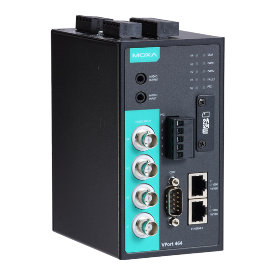
Overview The VPort 464 is a 4-channel Industrial Video Encoder with H.264/MJPEG video compression. The H.264 algorithm provides the best video quality on the market today with lower bandwidth requirements than other video compression standards. In addition, to meet requirements for multiple video streams, the VPort 464 can provide up to 3 video streams simultaneously with H.264 and MJPEG compression. - Page 3 • Select between Quad View/Full D1/ 4CIF/ VGA/ CIF/ QCIF resolutions. • 1 audio input and 1 audio output for 2-way voice communication. • TCP, UDP, and HTTP network transmission modes. • Supports Modbus/TCP for easy communication with SCADA systems. •...
- Page 4 VPort 464 Panel Layout 1. RS-232 console port 2. Hardware reset button 3. 8-pin terminal block for DI1, DI2, DI3, and DI4 4. 6-pin terminal block for, Relay 2, and power input 2 (PWR2) 5. Grounding screw 6. 6-pin terminal block for, Relay1, and power input 1 (PWR1) 7.
-
Page 5: First-Time Installation And Configuration
FAULT LED will light up red, providing the power failure alarm is enabled. NOTE The VPort 464 series supports power input specifications of 12-32 VDC for 12/24 VDC power input, or 18-30 VAC for 24 VAC power input. - Page 6 Step 4: Connecting motorized PTZ cameras and serial devices The VPort 464 has one COM PORT with a DB9 male connector, and the other is a PTZ PORT with 5-pin terminal block connector. Both ports can be used for connecting PTZ control cables for controlling PTZ cameras over the TCP/IP network.
- Page 7 NOTE You may download the VPort and EtherDevice Configurator software from Moxa’s website at www.moxa.com. 2. The Broadcast Search window will show a list of all switches and VPorts located on the network. The progress of the search will also be indicated.
- Page 8 NOTE Broadcast Search can only search for devices connected to the same LAN subnet as the VPort. If your devices are located on a different LAN subnet, use the “Specify IP Address” function to search for the device by keying in the IP address. 4.
- Page 9 Step 9: Install the ActiveX Control Plug-in A security warning message will appear the first time you access the VPort’s web-based manager. The message is related to installing the VPort ActiveX Control component to your PC or notebook. Click on Yes to install this plug-in to enable the ability to view video in the IE web browser.
-
Page 10: Mounting Dimensions
Step 11: Accessing the VPort’s System Configuration Click on System Configuration to access the overview of the system configuration to change the configuration. Model Name, Server Name, IP Address, MAC Address, Firmware Version, and LED Status appear in the green bar near the top of the page. Use this information to check the system information and installation. -
Page 11: Din-Rail Mounting
DIN-Rail Mounting The aluminum DIN-Rail attachment plate should already be attached to the back panel of the VPort 464 when you take it out of the box. Mount the VPort 464 on a mounting rail, as shown in the figures below. Step 1: Insert the upper lip of the DIN rail into the DIN-rail mounting... -
Page 12: Wiring Requirements
Step 2: Mounting VPort 464 on the wall requires 4 screws. Use the VPort 464, with wall mount plates attached, as a guide to mark the correct locations of the 4 screws. The heads of the screws should be less than 6.0 mm in diameter, and the shafts should be less than 3.5 mm in diameter, as shown in the figure on the right. -
Page 13: Wiring The Redundant Power Inputs
Grounding the Moxa VPort 464 Grounding and wire routing help limit the effects of noise due to electromagnetic interference (EMI). Run the ground connection from the ground screw to the grounding surface prior to connecting devices. ATTENTION This product is intended to be mounted to a well-grounded mounting surface, such as a metal panel. -
Page 14: Wiring The Relay Output
Wiring the Relay Output The VPort 464 has two sets of relay output, relay 1 and relay 2, which are located on the two 5-pin terminal block connectors. Each relay output consists of the 3 contacts of the terminal block on the VPort 464’s top panel. - Page 15 RS-232 Console Port Connection The VPort 464 has one RS-232 (10-pin RJ45) console port, located on the top panel. Use either an RJ45-to-DB9 or RJ45-to-DB25 cable (see the cable following wiring diagrams) to connect the VPort 464’s console port to your PC’s COM port. You may then use a console terminal program, such as the Moxa PComm Terminal Emulator, to access the VPort 464’s console configuration utility.
- Page 16 RJ45 (8-pin) to RJ45 (8-pin) Cross-over Cable Wiring COM Port A COM PORT is located on the front panel for connecting a PTZ motorized camera or serial device. The COM port transmits RS-232 or RS-422/485 signals over the TCP/IP network. Users can use this COM port (DB9 male connector) to monitor data or control a serial device, or for the control of a PTZ motorized camera.
-
Page 17: Microsd Card Slot
MicroSD Card Slot The front panel of Moxa’s VPort 464 has a MicroSD card slot that supports the SDHC interface. A MicroSD card can be used for recording video if the network is down. STEP 1: Open the upper case of the MicroSD card slot. -
Page 18: Led Indicators
LED Indicators The front panel of Moxa’s VPort 464 contains several LED indicators. The function of each LED is described in the table below. Color State Description Steady Hardware initialization stage. Flashing Software initialization stage. Green/ STATE Steady System is powered on and ready to run. Green Flashing Firmware is being upgraded. -
Page 19: Hardware Reset
Hardware Reset A recessed RESET button is provided for restoring the system to the factory default settings. When the system fails to install properly, or operates abnormally, use the RESET button located on the top panel of the VPort 464 to restore the factory defaults. To do this, use a pointed object such as a straightened paper clip or a toothpick, to depress the reset button continuously for about 90 seconds.
Need help?
Do you have a question about the VPort 464 Series and is the answer not in the manual?
Questions and answers