
Related Manuals for Moxa Technologies VPort 354


Summary of Contents for Moxa Technologies VPort 354
- Page 1 Moxa VPort 354 Industrial Video Encoder User’s Manual Third Edition, November 2011 www.moxa.com/product © 2011 Moxa Inc. All rights reserved.
- Page 2 Moxa VPort 354 Industrial Video Encoder User’s Manual The software described in this manual is furnished under a license agreement and may be used only in accordance with the terms of that agreement. Copyright Notice © 2011 Moxa Inc. All rights reserved.
- Page 3 Before using your VPort 354, please pay close attention to the following instructions: After opening the VPort 354 box, compare the contents of the box with the Package Checklist in Chapter 1. Notify your sales representative if any of the items are missing or damaged.
-
Page 4: Table Of Contents
Overview ............................1-2 Package Checklist ..........................1-3 Product Features ..........................1-4 Typical Application ..........................1-5 Panel Layout of the VPort 354 ......................1-6 Product Description ..........................1-7 Getting Started..........................2-1 Before Getting Started ........................2-2 First-Time Installation and Configuration ....................2-2 RS-232 Console Configuration (115200, None, 8, 1, VT1 00) ............ - Page 5 Video ............................4-21 Image Settings ........................4-21 Camera Modulation ......................4-22 Video Performance ......................4-22 Camera Control ......................... 4-24 Serial Port ..........................4-25 PTZ port ........................... 4-26 COM port .......................... 4-28 Parameters ........................4-31 Audio ............................4-31 Audio Source ........................4-31 Alarm ............................
-
Page 6: Introduction
Introduction The VPort 354 is a rugged networking video encoder designed for use in harsh environments. In addition to being able to handle basic video feeds, many advanced features are also included to set up surveillance or web multimedia applications. The VPort 354 is designed to provide stability, robustness, ease-of-use, and flexibility. -
Page 7: Overview
An Ethernet bypass function is also supported so the cascade network will keep working even if one of the VPort 354 units in the cascade chain goes offline. Port redundancy can be used to build a backup path for video transmission in case the primary path is unavailable. -
Page 8: Package Checklist
SDK requirements, please contact a Moxa sales representative for details and an application form. Package Checklist The Moxa VPort 354 is shipped with the following items. If any of these items are missing or damaged, please contact your sales representative for assistance. -
Page 9: Product Features
VPort 354 Introduction Product Features High Performance Video/Audio Networking Solution • Works with NTSC/PAL analog video cameras • Supports MPEG4/MJPEG video compression technologies • 4 BNC video inputs • Video stream up to 120 frames/sec in 4CIF (704 x 480) resolution through a total of 4 channels •... -
Page 10: Typical Application
VPort 354 Introduction Typical Application... -
Page 11: Panel Layout Of The Vport 354
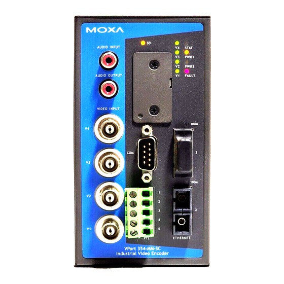
VPort 354 Introduction Panel Layout of the VPort 354 1. Grounding screw 2. RS-232 console port 3. Hardware reset button 4. 8-pin terminal block for Relay 1, Relay 2, and power input 2 (PWR2) 5. 10-pin terminal block for DI 1, DI 2, DI 3, DI 4, power input 1 (PWR1) 6. -
Page 12: Product Description
RCA phone jacks for audio input/output The VPort 354 has 2 RCA phone jacks for audio input and output on the front panel. One jack is for a MIC-in/Line-in audio input connection, which can be directly connected with a microphone or an audio source from an amplifier. - Page 13 VPort 354 Introduction RS-232/RS-422/RS-485 PTZ port The VPort 354 has 1 PTZ port for PTZ control. This PTZ port is an RS-232/RS-422/485 serial port with a 5 pin terminal block connector. The pin assignments are as follows: RS-422/485 RS-232 Ground...
- Page 14 SD card slot for local storage capability The front panel of Moxa’s VPort 354 has an SD card slot that supports the SDHC interface. An SD card can be used for recording video if the network is down. Currently, the maximum SD capacity is 32GB, which is supported by the VPort 354.
- Page 15 1. Reboot: To reboot the VPort 354, power it off and then power it back on again, or push the RESET button one time. The STAT LED will light in red as the POST (Power On Self Test) process runs. When the rebooting process is finished, the STAT LED will turn green.
-
Page 16: Getting Started
Getting Started This chapter includes information about how to install a VPort 354 video encoder. The following topics are covered in this chapter: Before Getting Started First-Time Installation and Configuration RS-232 Console Configuration (115200, None, 8, 1, VT1 00) ... -
Page 17: Before Getting Started
Select the power source The VPort 354 can be powered by a 12 to 32 VDC DC power input, or a 18 to 30 VAC AC power input. Two power inputs are provided for redundancy. Users can check the LED status located in the front panel to see if the power inputs are connected appropriately. - Page 18 Connecting motorized PTZ cameras and serial devices The VPort 354 has 2 RS-232/422/485 ports. One is a COM PORT with a DB9 male connector, and the other is a PTZ PORT with a 5-pin terminal block connector. Both ports can be used for connecting PTZ control cables to control PTZ cameras over the TCP/IP network.
- Page 19 Configure the VPort 354’s IP address After powering on the VPort 354, wait a few seconds for the POST (Power On Self Test) to run. The STAT LED turns green to indicate that the POST process has completed. The IP address will be assigned when the 10 or 100 Mbps NETWORK LED blinks.
- Page 20 Network Environment without a DHCP Server: If your VPort 354 is connected to a network that does not have a DHCP server, then you will need to configure the IP address manually. The default IP address of the VPort 354 is 192.168.127.100 and the default subnet...
- Page 21 Step 8: Accessing the homepage of the VPort 354’s web-based manager After installing the ActiveX Control component, the homepage of the VPort 354’s web-based manager will appear. Check the following items to make sure the system was installed properly: 1. Video Images 2.
- Page 22 VPort 354 Getting Started Step 9: Accessing the VPort’s System Configuration Click on System Configuration to access the overview of the system or to change the settings. Model Name, Server Name, IP Address, MAC Address, Firmware Version, and LED Status appear in the green bar near the top of the page.
-
Page 23: Rs-232 Console Configuration (115200, None, 8, 1, Vt1 00)
PComm Terminal Emulator, which is free and can be downloaded from Moxa’s website. The following instructions explain how to use PComm to access the RS-232 console. 1. Use an RJ45 to DB9-F (or RJ45 to DB25-F) cable to connect the VPort 354’s RS-232 console port to a COM port on your PC. - Page 24 VPort 354 Getting Started 4. The Communication Parameter page of the Property window opens. Select the appropriate COM port for Console Connection, 115200 for Baud Rate, 8 for Data Bits, None for Parity, and 1 for Stop Bits. 5. Click the Terminal tab, and select VT100 for Terminal Type. Click OK to continue.
- Page 25 VPort 354 Getting Started as the password. Press Enter to continue. 7. The RS-232 console’s Main Menu will be displayed. (NOTE: To modify the appearance of the PComm Terminal Emulator window, select Font... under the Edit menu, and then choose the desired formatting options.) 8.
-
Page 26: Mounting The Vport 354 Dimension
DIN-Rail Mounting The DIN-Rail attachment plate should already be attached to the back panel of the VPort 354 when you take it out of the box. If you need to reattach the plate, make sure the metal spring is situated towards the top, as shown in the figures below. -
Page 27: Wall Mounting
NOTE Follow the steps below to mount the VPort 354 on a wall or panel. STEP 1: Remove the DIN-Rail attachment plate from the VPort 354. Attach the two wall-mount plates as shown in the diagrams below. ⇒ STEP 2: 4 screws are required. -
Page 28: Wiring Requirements
Wiring the Redundant Power Inputs The VPort 354 has two sets of power inputs, power input 1 and power input 2, which are located on the 10-pin and 8-pin terminal block connectors. Top and front views of the terminal block connectors are shown here. -
Page 29: Wiring The Relay Output
Wiring the Digital Inputs The VPort 354 has four sets of digital inputs, DI1, DI2, DI3 and DI4. Each DI consists of two contacts of the 10-pin terminal block connector on the VPort’s top panel. Top and front views of one of the terminal block connectors are shown here. -
Page 30: 10/100Baset(X) Ethernet Port Connection
Getting Started RS-232 Connection The VPort 354 has one RS-232 (10-pin RJ45) console port, located on the top panel. Use either an RJ45-to-DB9 or RJ45-to-DB25 cable (see the cable following wiring diagrams) to connect the VPort 354’s console port to your PC’s COM port. -
Page 31: 100Basefx Ethernet Port Connection
SC-Port Pinouts SC-Port to SC-Port Cable Wiring The 2 Ethernet ports on the VPort 354’s front panel can be used as cascade links or to provide port redundancy. NOTE When used as cascade links, you will need to calculate the number of video streams in order to optimize the transmission bandwidth. -
Page 32: Com Port
PTZ Port A PTZ port is located on the VPort 354’s front panel. The port is used to connect to a PTZ motorized camera or device, so that the camera or device can be controlled from the VPort over the IP network. The PTZ port supports RS-232 or RS-422/485 signals through the terminal block. - Page 33 SD card. If the SD LED indicator flashes red, it means the unmounting of the SD card failed. At this point, you can remove the SD card, but you will need to reboot the VPort 354 to enable the SD card slot function for future SD cards.
-
Page 34: Accessing The Vport 354'S Web-Based Manager
Accessing the VPort 354’s Web-based Manager This chapter includes information about how to access the VPort 354 Video Encoder for the first time. The following topics are covered in this chapter: Functions Featured on the VPort’s Web Homepage VPort’s Information ... -
Page 35: Functions Featured On The Vport's Web Homepage
VPort 354 Accessing the VPort 354’s Web-based Manager Functions Featured on the VPort’s Web Homepage The homepage of the VPort’s web console shows information specific to that VPort, the camera image, and configurations for the client and server. The VPort’s web homepage is best viewed in 1280 x 1024 screen resolution. This is because the camera image NOTE can be viewed at a resolution up to Full D1 (NTSC: 720 x 480;... -
Page 36: Audio Control
Manager Audio Control The VPort 354 provides both audio input and audio output for voice over IP communication. Client users can directly enable and disable the audio input (a microphone, for example) by clicking the microphone button and the audio output (a speaker, for example) by clicking the speaker button from the VPort’s web homepage. You may also use the Client Setting to disable the audio transmission. -
Page 37: System Configuration
VPort 354 Accessing the VPort 354’s Web-based Manager System Configuration A button or text link on the left side of the system configuration window only appears on the administrator’s main page. For detailed system configuration instructions, refer to Chapter 4, System Configuration. -
Page 38: Ptz (Motorized) Camera Control
Relay Control The VPort 354 has 2 relay outputs for external devices, such as alarms. Administrators and permitted users can click on Open to short the Common and Normal Open digital output pins, or click on Close to short the... -
Page 39: System Configuration
System Configuration After installing the hardware, the next step is to configure the VPort 354’s settings. Users can configure by web console. The following topics are covered in this chapter: System Configuration by Web Console System Network ... -
Page 40: System Configuration By Web Console
VPort 354 System Configuration System Configuration by Web Console System configuration can be done remotely with Internet Explorer. To access the server, type the system configuration URL, http://<IP address of Video Server>/setup/config.html, to open the configuration main page. There are six configuration categories: System, Network, Video, Serial Port, Audio, and Alarm. A... -
Page 41: System
Server name Setting Description Default Max. 40 characters Use a different server name for each server to help identify the VPort 354 4CH Video different servers. The name appears on the web homepage. Encoder Date and Time Setting Description Default Keep current date and Use the current date and time as the VPort’s time setting. -
Page 42: Account Privileges
VPort 354 System Configuration Manual Manually change VPort’s date and time setting. Automatic Use the NTP server for changing VPort’s date and time setting in a given period. NOTE Select the Automatic option to force the VPort to synchronize automatically with timeservers over the Internet. -
Page 43: Local Storage
The FPS of the video stream will be reduced as more and more users access the same VPort. Currently, the NOTE VPort 354 is only allowed to send 8 unicast video streams and 4 multicast video streams at the same time. Therefore, limit the number of users simultaneously accessing a VPort 354 to prevent performance problems. -
Page 44: System Diagnosis
VPort 354 System Configuration System Diagnosis VPort products have a self-diagnosis function to let the administrator get a quick view of the system and connection status. Administrators can save this diagnosis information in a file (diagnosis.log) by clicking the Export to a File button, or send the file via email by clicking the Send a Report via Email button. -
Page 45: System Parameters
Take the following steps to upgrade the firmware: Step 1: Press the Browse button to select the firmware file. NOTE For the VPort 354, the firmware file extension should be .rom. Click on the Upgrade button to upload the firmware to the VPort. Step 2: Step 3: The system will start to run the firmware upgrade process. -
Page 46: Reset To Factory Default
VPort 354 System Configuration Reset to Factory Default From the “Reset to Factory Default” page, click on OK (as shown in the following figure) to reset the VPort to its factory default settings. All parameters will be reset to factory defaults when you use the Factory Default function. For this reason, if NOTE you want to keep a digital copy of the current configuration, remember to export the sys_config.ini file before... - Page 47 The VPort 354 supports standard RTSP (Real Time Streaming Protocol) streaming, which means that all devices and software that support RTSP can directly acquire and view the video images sent from the VPort 354 without any proprietary codec or SDK installations. This makes network system integration much more convenient. For different connection types, the access name is different.
- Page 48 354’s IP address>[:<RTSP Port]/udpstream_ch<channel number> rtsp://<VPort 354’s IP address>[:<RTSP Port]/multicaststream_ch<channel number> RTSP Port: 554 Is default, and then click on OK to connect to the VPort 354. Wait a few seconds for QuickTime Player to establish the connection. Step 3: Step 4: After the connection has been established, the VPort 354’s video will appear in the QuickTime Player...
-
Page 49: Smtp Server And Email Account Settings
System Configuration NOTE The video performance of the VPort 354 may vary when using other media players. For example, you will notice a greater delay when viewing the VPort 354’s video from the QuickTime player compared to viewing it directly from the VPort 354’s built-in web server. -
Page 50: Ftp Server Settings
VPort 354 System Configuration Two recipient email accounts are available for receiving emails sent by the VPort. For redundancy, both addresses receive the sent messages and alarm snapshots simultaneously. Setting Description Default 1st Recipient’s Email Email address of the 1st recipient. -
Page 51: Dynamic Dns
VPort 354 System Configuration Dynamic DNS DDNS (Dynamic Domain Name System) is a combination of DHCP, DNS, and client registration. DDNS allows administrators to alias the VPort’s dynamic IP address to a static hostname in any of the domains provided by the DDNS service providers listed on the VPort’s Network/DDNS configuration page. DDNS makes it easier to access the VPort from various locations on the Internet. -
Page 52: Multicast
Enable or disable the UPnP function. Enabled Multicast The VPort 354 supports the advanced Multicast network protocol IGMP, which can greatly improve the efficiency of network traffic. In this section, we explain multicasts, multicast filtering, and how multicast can be implemented on your VPort. -
Page 53: Configuring Multicast Settings
The network WITH Multicast NOTE The VPort 354 is the source that delivers the multicast video stream. To benefit from the Multicast protocol, the gateway or network switch should support the multicast filtering function (such as IGMP Snooping) so that the multicast stream is delivered correctly and precisely. -
Page 54: Accessible Ip List
192.168.1.128/255.255.255.128 SNMP The VPort 354 supports three SNMP protocols. The available protocols are SNMP V1, SNMP V2c, and SNMP V3. SNMP V1 and SNMP V2c use a community string match for authentication, which means that SNMP servers access all objects with read-only or read/write permissions using the community string public/private (default value). -
Page 55: Configuring Snmp Settings
VPort 354 System Configuration levels supported by the VPort are shown in the following table. Select one of these options to communicate between the SNMP agent and manager. Protocol Security Authentication Data Method Version Mode Type Encryption V1, V2c Read... - Page 56 VPort 354 System Configuration V1, V2c Read Community Setting Description Default V1, V2c Read Use a community string match for authentication, which means public Community that the SNMP agent accesses all objects with read-only (max. 30 permissions using the community string public.
-
Page 57: Qos (Tos)
VPort 354 System Configuration Private MIB information The private SNMP Object ID of the VPort is the enterprise value: 8691.8.1.6. This number cannot be changed. NOTE The MIB file is MOXA-VPORT354-MIB.my. You can find it on the software CD or the download center of the Moxa website. -
Page 58: Modbus/Tcp
VPort 354 System Configuration http:// http event server:Port/CGI_Name User name The account name for accessing the HTTP server None Password The password for accessing the HTTP server None Once the Http Alarm is triggered, the VPort will send the following HTTP commands to the HTTP event servers. -
Page 59: Video
VPort 354 System Configuration The 2 Ethernet ports on the VPort 354’s front panel can be used as cascade links or to provide port redundancy. NOTE When used as cascade links, you will need to calculate the number of video streams in order to optimize the transmission bandwidth. -
Page 60: Camera Modulation
Video Performance The VPort 354 can send the MPEG4 and MJEPG video streams simultaneously. But both video streams are will have the same image resolution and frame rate. The administrator can set up the Resolution, Max. Frame Rate, Video Quality, and Enable Snapshot in this web page. - Page 61 The administrator can enable or disable the video channel to Enabled video channel show or not show the video image. Resolution The VPort 354 supports 5 different resolutions: 4CIF, 2CIF, CIF, 2/3 CIFand QCIF. Setting Description Default Select the image size 5 image resolutions (size) are provided.
-
Page 62: Camera Control
VPort 354 System Configuration Key Frame Interval With MPEG4, the key frame plays an important role in deciding the video quality. The key frame interval indicates how many frames are required for the VPort to get a key frame. A smaller “key frame interval” means better video quality, but the bandwidth will be increased since the key frame image size is larger than other frames. -
Page 63: Serial Port
Serial Port The VPort 354 has 2 serial ports. One is the PTZ port and the other is the COM port. Both ports can be set for RS-232, RS-422, or RS-485. Refer to the Quick Installation Guide or Chapter 2 for the connector type and pin assignment. -
Page 64: Ptz Port
VPort 354 System Configuration PTZ port This PTZ port is used to control a PTZ camera. Interface mode Setting Description Default Select the serial The PTZ port supports 3 serial interfaces, although only one RS485 interface interface can be used at a time. Depending on the interface used by the attached device, administrators must set the Interface mode to either RS-232, RS-422, or RS485. - Page 65 VPort 354 System Configuration NOTE The legacy PTZ control panel or joystick should be connected to the VPort’s PTZ port or the COM port of a PC. But, when it is connected to a PC’s COM port, you will need to install a real COM driver on the PC and map the COM ports.
-
Page 66: Com Port
VPort 354 System Configuration Setting Up a Custom Camera If the PTZ camera’s driver is not in the list, the administrator can select the custom camera from the Select Camera driver menu to program the PTZ camera with ASCII code. A custom camera window will pop up when the Setup Custom Camera button is clicked. - Page 67 VPort 354 System Configuration Interface mode Setting Description Default Select the serial The COM port supports 3 serial interfaces, although only one RS485 interface interface can be used at a time. Depending on the interface used by the attached device, administrators must set the Interface mode to either RS-232, RS-422, or RS-485.
- Page 68 VPort 354 System Configuration Port Settings (only available in Serial Device Control) Setting Description Default Operation Mode Select the serial device control operation modes via the TCP/IP Real COM Mode network: Real COM Mode, TCP Server Mode, TCP Client Mode...
-
Page 69: Parameters
VPort 354 System Configuration Parameters Some COM port parameters need to be configured. Port Settings Setting Description Default Baud rate (bps) The baud rate specified by the PTZ camera’s serial 2400 communication specs. Data bits The parameters used to define the serial communication. -
Page 70: Alarm
VPort 354 System Configuration Alarm System Alarm In addition to the LED indicators, three kinds of system alarms are provided by the VPort 354 for notifying the system operations administrator. Alarm Type Triggered Condition Triggered Action Power 1 failure Relay... -
Page 71: Event Alarm
VPort 354 System Configuration Event Alarm Four kinds of event alarm are provided by the VPort for building an intelligent video surveillance system. Alarm Type Triggered Condition Triggered Action 1. VMD 1 1. Relay Video Motion Detection (VMD) 2. VMD 2 2. -
Page 72: Schedule
VPort 354 System Configuration seconds(s) before the seconds before the event alarm is (from 1 to 6 event triggered. seconds) Take snapshot A snapshot image is taken this number of 11 seconds seconds(s) after the seconds after the event alarm is triggered. -
Page 73: Video Motion Detection
VPort 354 System Configuration Weekly Schedule Setting Description Default Event Alarms are active Select the option “Event Alarms are active all the time” Event Alarms are all the time active based on a weekly schedule Event Alarms are active Select to operate event alarms on a weekly schedule. - Page 74 VPort 354 System Configuration Setting Description Default Enable VMD alarm Enable or disable the Video Motion Detection alarm Disabled Show alert on the Enable or disable to show the alert, which is a red squre frame, Disabled image when VMD is...
- Page 75 VPort 354 System Configuration Once the Show alert on the image when VMD is triggered is enabled, the red frames that appear on the NOTE homepage image indicate the size of the VMD window set up by the administrator Setup a VMD Alarm...
-
Page 76: Digital Input
VPort 354 System Configuration Trigger Conditions and Actions Administrators can set up triggers for each VMD, including Trigger Relay1 alarm, Trigger Relay2 alarm, Send snapshot image via E-mail, Send snapshot image via FTP, and Send Message via HTTP Event servers. - Page 77 VPort 354 System Configuration Trigger Conditions Setting Description Default High The DI is always in the “High” state after an alarm is detected. Disabled The DI is always in the “Low” state after an alarm is detected. Enabled Rising The DI works from state “Low” to state “High” and then back to Disabled state “Low”...
-
Page 78: Video Loss
VPort 354 System Configuration Video Loss The Video Loss event means that the VPort cannot detect the analog video signal. Video Loss Trigger Actions Setting Description Default Enable video loss alarm Enable or disable video loss alarm. Disabled Channel Select the Channel 1, 2, 3, 4... -
Page 79: Cgi Event
VPort 354 System Configuration CGI Event The VPort can accept 5 CGI commands, which are sent from external devices, such as ioLogik series Ethernet I/O, to be the event alarms. The VPort only can accept the CGI commands that follow the VPort’s CGI commands format. - Page 80 VPort 354 System Configuration 4-42...
-
Page 81: Frequently Asked Questions
Basically, there is no limitation. However the video quality also depends on the network. To achieve the best effect, the VPort 354 video encoder will allow 8 video streams for udp/tcp/http connections, and 4 multicast video streams. We recommend using an additional web server that retrieves images from the... - Page 82 VPort 354 Frequently Asked Questions What is the video encoder’s video rate? The MPEG4 codec can process 30 frames per second internally. However the total performance is subject to many variables, as listed below: • Network throughput. • Bandwidth share.
-
Page 83: Settings Of Supported Ptz Cameras
Settings of Supported PTZ Cameras Since the COM port settings can be adjusted to other than the default settings, check the correct default settings for the attached camera. Camera model Baud rate Data bits Stop bit Parity bit Pelco P, D protocol 2400 None DynaDome/DynaDome... -
Page 84: Time Zone Table
Time Zone Table The hour offsets for different time zones are shown below. You will need this information when setting the time zone in automatic date/time synchronization. GMT stands for Greenwich Mean Time, which is the global time that all time zones are measured from. (GMT-12:00) International Date Line West (GMT-11:00) - Page 85 VPort 354 Time Zone Table (GMT+03:00) Nairobi (GMT+03:30) Tehran (GMT+04:00) Abu Dhabi, Muscat (GMT+04:00) Baku, Tbilisi, Yerevan (GMT+04:30) Kabul (GMT+05:00) Ekaterinburg (GMT+05:00) Islamabad, Karachi, Tashkent (GMT+05:30) Chennai, Kolkata, Mumbai, New Delhi (GMT+05:45) Kathmandu (GMT+06:00) Almaty, Novosibirsk (GMT+06:00) Astana, Dhaka (GMT+06:00)
-
Page 86: Technical Specifications
Technical Specifications Video Video Compression: MJPEG or MPEG4 (ISO/IEC 14496-2) Video Inputs: 4, BNC connector (1.0 Vpp, 75 ohm) Video Outputs: Via Ethernet port Video Streams: Dual streams (one for MJPEG, the other for MPEG4) at the same video resolution (note that MJPEG only has one quality setting) NTSC/PAL: Manual Video Resolution and FPS (frames per second):... - Page 87 VPort 354 Technical Specifications Power Requirements Input Voltage: 2 12/24 VDC or 24 VAC inputs for redundancy Power Consumption: Approx. 12 W Physical Characteristics Housing: Metal, IP30 protection Dimensions: 80.2 x 135 x 105 mm (3.16 x 5.31 x 4.13 in) Weight: 1200 g (2.64 oz)
- Page 88 VPort 354 Technical Specifications Software Development Kit VPort SDK PLUS: Includes CGI commands, ActiveX Control, and API library for customized applications or system integration for third-party developers (the latest version of SDK is vailable for download from Moxa’s website).
Need help?
Do you have a question about the VPort 354 and is the answer not in the manual?
Questions and answers