
Related Manuals for Speco O6MDP3N


Summary of Contents for Speco O6MDP3N
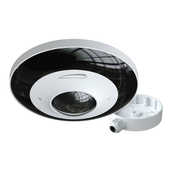
- Page 1 User Manual 6MP Panoramic Network Camera O6MDP3N Please read this instruction carefully before operating the unit and keep it for further reference...
- Page 2 Important Safeguards and Warnings 1. Electrical safety All installation and operation here should conform to local electrical safety codes. Use a certified/listed 12VDC Class2 power supply only. Please note: Do not connect two power supplying sources to the device at the same time; it may result in device damage! The product must be grounded to reduce the risk of electric shock.
- Page 3 Statement This guide is for reference only. Product, manuals and specifications may be modified without prior notice. Speco Technologies reserves the right to modify these without notice and without incurring any obligation. Speco Technologies is not liable for any loss caused by improper operation.
-
Page 4: Table Of Contents
Table of Contents Introduction ..........................................2 Web Access and Login ......................................3 Live View..........................................4 Camera Configuration ......................................8 System Configuration ................................8 4.1.1 System Information ..............................8 4.1.2 Date and Time ................................8 4.1.3 Local Recording ................................9 4.1.4 Storage .................................. - Page 5 5.2.1 Local Video Search ..............................33 5.2.2 SD Card Video Search..............................34 Appendix ............................................36 Appendix 1 Troubleshooting ......................................36...
-
Page 6: Introduction
Thank you for purchasing this network camera! Please read this manual carefully before operating the unit and retain it for further reference. Should you require any technical assistance, please contact Speco Technologies Technical Support at 1-800-645-5516. Main Features Built-in PoE (Power over Ethernet) ... -
Page 7: Web Access And Login
2 Web Access and Login The IP camera settings can be accessed via a web browser (Internet Explorer 8 and up) through the LAN. Access through IP Scanner Network connection: ①Make sure the PC and IP-Cam are connected on the same local network. The camera is set to DHCP by default and will be assigned an IP address by the DHCP server. -
Page 8: Live View
3 Live View The window below will be shown after logging in. Before you view the live image, please set the stream mode and installation method as needed (see Configuring Fisheye Parameters for details). The following table describes the icons on the live view interface. Icon Description Icon... - Page 9 Fisheye+ 3PTZ view mode Panoramic + 3PTZ view mode...
- Page 10 4PTZ view mode (you need to switch the stream mode in the fisheye parameter interface) In panoramic + 3PTZ view mode or fisheye + 3PTZ view mode or 4PTZ view mode, select a PTZ window and view the image from every direction by controlling PTZ panel.
- Page 11 Move lower left direction Move lower right direction Move down Speed adjustment Zoom out Zoom in Focus - Focus + Iris - Iris + Auto scan Wiper Light Radom scan Group scan Preset Select preset and click to call the preset. Select and set the preset and then click to save the position of the preset.
-
Page 12: Camera Configuration
4 Camera Configuration Press the “Setup” button to go to the configuration interface. Note: Wherever applicable, click the “Save” button to save the settings. 4.1 System Configuration 4.1.1 System Information In the “System Information” interface, the system information of the device is listed. 4.1.2 Date and Time To set the time and date, go to SystemDate and Time. -
Page 13: Local Recording
4.1.3 Local Recording Go to SystemLocal Recording to set up the storage path of captured pictures and recorded videos on the local PC. There is also an option to enable or disable the bitrate display in the recorded files. Additionally, the snapshots triggered by smart events (including face detection, line crossing detection and intrusion detection) can be selected to save to the local PC. - Page 14 2. Set record stream, pre-record time and cycle writing. Pre Record Time: Set the time to record before the actual recording begins. 3. Set schedule recording. Check “Enable Schedule Record” and set the schedule. Weekly schedule Set the alarm time from Monday to Sunday for a single week. Each day is divided in one hour increments. Green means scheduled. Blank means unscheduled.
-
Page 15: Configuring Fisheye Parameters
Set the format, resolution and quality of the image saved on the SD card and the snapshot interval and quantity and the timing snapshot here. Snapshot Quantity: The number you set here is the maximum quantity of snapshots. The actual quantity of snapshots may be less than this number. - Page 16 Brightness: Set the brightness level of the camera’s image. Contrast: Set the color difference between the brightest and darkest parts. Hue: Set the total color degree of the image. Saturation: Set the degree of color purity. The purer the color, the brighter the image is. WDR: WDR can adjust the camera to provide a better image when there are both very bright and very dark areas simultaneously in the field of the view by lowering the brightness of the bright area and increasing the brightness of the dark area.
-
Page 17: Video / Audio Configuration
Set full time schedule for common, day or night mode and specified time schedule for day and night. Choose “Timing” in the drop-down box of schedule as shown below. Drag “ ” icons to set the time of day and night. Blue means day time and blank means night time. If the current mode of camera parameters is set to “Timing”, the image configuration mode will automatically switch between day and night according to the schedule. -
Page 18: Osd Configuration
scene changes. For example, for scenes that do not have much movement, the bitrate will be kept at a lower value. This can help optimize the network bandwidth usage. Bitrate: it can be adjusted when the mode is set to CBR. The higher the bitrate, the better the image quality will be. Video Quality: It can be adjusted when the mode is set to VBR. -
Page 19: Video Mask
4.2.4 Video Mask Go to ImagePrivacy Mask interface as shown below. A maximum of 4 zones can be set up. To set up video mask: 1. Enable video mask. 2. Click the “Draw Area” button and then drag the mouse to draw the video mask area. 3. -
Page 20: Ptz Configuration
1. Check “Enable” and then click the “Draw Area” button. 2. Drag the mouse to set the ROI area. 3. Set the level. 4. Click the “Save” button to save the settings. 4.3 PTZ Configuration Go to PTZProtocol interface. The PTZ of this camera can be controlled by the keyboard. Connect the keyboard and the camera through RS485 interface and then set the corresponding protocol and baud-rate in the camera and keyboard. -
Page 21: Other Alarms
1. Check “Enable” check box to activate motion based alarms. If unchecked, the camera will not send out any signals to trigger motion-based recording to the NVR or CMS, even if there is motion in the video. Alarm Out: If selected, this would trigger an external relay output that is connected to the camera on detecting a motion based alarm. - Page 22 2. Click “Enable” and set the alarm holding time. 3. Set alarm trigger options. The setup steps are the same as motion detection. Please refer to motion detection chapter for details. SD Card Error When there are some errors in writing SD card, the corresponding alarms will be triggered. 1.
-
Page 23: Alarm In (Sensor Input)
2. Click “Enable” and set the alarm holding time. 3. Trigger alarm out. When the camera is disconnected, the system will trigger the alarm out. 4.4.3 Alarm In (Sensor Input) This function is only available for some models. To set sensor alarm (alarm in): Go to Event SetupAlarm In interface as shown below. -
Page 24: Alarm Server
Alarm Out Mode: Alarm linkage, manual operation, day/night switch linkage and schedule are optional. Alarm Linkage: Having selected this mode, select alarm out name, alarm holding time at the “Alarm Holding Time” pull down list box and alarm type. Manual Operation: Having selected this mode, select alarm type and click “Open” to trigger the alarm out immediately; click “Close” to stop alarm. -
Page 25: Network Configuration
4.5 Network Configuration 4.5.1 TCP/IP Go to NetworkTCP/IP interface as shown below. There are two ways for network connection. Use IP address (take IPv4 for example)-obtain a local IP address automatically through DHCP. A typical router has a DHCP server built in, and therefore is able to assign an IP address to the camera. -
Page 26: Port
4.5.2 Port Go to NetworkAdvanced interface as shown below. HTTP port, Data port and RTSP port can be set. HTTP Port: The default HTTP port is 80. It can be changed to any port which is not occupied. HTTPS Port: The default HTTPs port is 443. It can be changed to any port which is not occupied. Data Port: The default data port is 9008. -
Page 27: Snmp
4.5.5 SNMP To get camera status, parameters and alarm information and remotely manage the camera, the SNMP function can be used. Before using SNMP, please install an SNMP management tool and set the parameters of the SNMP, such as SNMP port, trap address. 1. -
Page 28: 802.1X
4.5.6 802.1x If it is enabled, the camera’s data can be protected. When the camera is connected to the network protected by the IEE802.1x, user authentication is needed. To use this function, the camera shall be connected to a switch supporting 802.1x protocol. The switch can be reckoned as an authentication system to identify the device in a local network. -
Page 29: Upnp
RTSP Address: The RTSP address (unicast) format that can be used to play the stream in a media player. Multicast Address Main stream: The address format is “rtsp://IP address: rtsp port/profile1?transportmode=mcast”. Sub stream: The address format is “rtsp://IP address: rtsp port/profile2?transportmode=mcast”. Third stream: The address format is “rtsp://IP address: rtsp port/profile3?transportmode=mcast”. -
Page 30: Ftp
Click the “Test” button to test the connection of the account. Recipient Address: receiver’s e-mail address. 4.5.10 FTP After an FTP server is set up, captured pictures from events will be uploaded to the FTP server. Go to NetworkFTP. Server Name: The name of the FTP server. Server Address: The IP address or domain name of the FTP. -
Page 31: Qos
* If there is a signed certificate, click “Browse” to select it and then click “Install” to install it. * Click “Create a private certificate” to enter the following creation interface. Click the “Create” button to create a private certificate. Enter the country (only two letters available), domain (camera’s IP address/domain), validity date, password, province/state, region and so on. -
Page 32: Security Configuration
4.6 Security Configuration 4.6.1 User Admin Go to SecurityUser Admin interface as shown below. Add user: 1. Click “Add” to pop up the following textbox. 2. Enter user name in “User Name” textbox. 3. Enter letters or numbers in “Password” and “Confirm Password” textbox. 4. -
Page 33: Online User
3. Enter the old password of the user in the “Old Password” text box. 4. Enter the new password in the “New password” and “Confirm Password” text box. 5. Enter computer’s MAC address as necessary. 6. Click the “OK” button to save the settings. Note: To change the access level of a user, the user must be deleted and added again with the new access level. -
Page 34: Security Management
4.6.4 Security Management Go to SecuritySecurity Management as shown below. In order to prevent against malicious password unlocking, “locking once illegal login” function can be enabled here. If this function is enabled, login failure after trying six times will make the login interface locked. The camera can be logged in again after a half hour or after the camera reboots. -
Page 35: Upgrade
4.7.3 Upgrade Go to MaintenanceUpgrade. In this interface, the camera firmware can be updated. 1. Click the “Browse” button to select the save path of the upgrade file 2. Click the “Upgrade” button to start upgrading the firmware. 3. The device will restart automatically Caution! Do not close the browser or disconnect the camera from the network during the upgrade. -
Page 36: Search
5 Search 5.1 Image Search In the Setup interface, click Search to go to the interface as shown below. Images that are saved on the PC or SD card can be found here. Local Image Search Set time: Select date and choose the start and end time in the top left corner. Click “Search”... -
Page 37: Video Search
The descriptions of the buttons are shown as follows. Icon Description Icon Description Close: Select an image and click Close all: Click this button to close all this button to close the image. images. Save: Click this button to select the Save all: Click this button to select the path for saving the image on the path for saving all pictures on the PC. -
Page 38: Sd Card Video Search
Choose the date and the start time and end time and then click “Search” button to search the record files. Double click the record file to play the record. Icon Description Icon Description Play button. After pausing the video, Pause button click this button to continue playing. - Page 39 1. Set the date and the start and end time, select the record type and then click “Search” button to search the record. 2. Double click the searched file name to play the record. Please refer to Local Video Search for the descriptions of the buttons on the playback interface. Click button to download the record saved in the SD card.
-
Page 40: Appendix
Appendix Appendix 1 Troubleshooting IP Scanner does not show any device. Make sure that the PC that’s running IP Scanner is on the same local network as the devices. Internet Explorer cannot download ActiveX control. IE browser may be set up to block ActiveX. Follow the steps below. 1. - Page 41 Models:O6MDP3N Federal Communications Commission (FCC) Statements This device complies with Part 15 of the FCC Rules. Operation is subject to the following two conditions: (1) This device may not cause harmful interference, and (2) This device must accept any interference received, including interference that may cause undesired operation.
Need help?
Do you have a question about the O6MDP3N and is the answer not in the manual?
Questions and answers