Tektronix MSO 4 Series Quick Start Manual
Hide thumbs
Also See for MSO 4 Series:
- Help manual (768 pages) ,
- Installation and safety (73 pages) ,
- Manual (43 pages)

Related Manuals for Tektronix MSO 4 Series


Summary of Contents for Tektronix MSO 4 Series
- Page 1 4 Series MSO MSO44, MSO46 Quick Start Manual Register now! Click the following link to protect your product. www.tek.com/register *P077178300* 077-1783-00...
- Page 2 Copyright © Tektronix. All rights reserved. Licensed software products are owned by Tektronix or its subsidiaries or suppliers, and are protected by national copyright laws and international treaty provisions. Tektronix products are covered by U.S. and foreign patents, issued and pending. Information in this publication supersedes that in all previously published material. Specifications and price change privileges reserved.
-
Page 3: Table Of Contents
Table of Contents Table of Contents Important safety information................................5 General safety summary................................5 To avoid fire or personal injury............................... 5 Probes and test leads................................7 Service safety summary.................................7 Terms in this manual................................8 Terms on the product................................8 Symbols on the product................................. 8 Compliance information................................ - Page 4 Table of Contents Autoset to quickly display a waveform..........................48 How to trigger on a signal..............................48 Set the acquisition mode..............................49 Set Horizontal parameters ..............................50 Add a math, reference, or bus waveform..........................51 Add a measurement................................52 Configure a measurement..............................54 Add a plot of a measurement...............................54 Add a Search..................................
-
Page 5: Important Safety Information
Do not connect or disconnect probes or test leads while they are connected to a voltage source. Use only insulated voltage probes, test leads, and adapters supplied with the product, or indicated by Tektronix to be suitable for the product. - Page 6 Be sure your work area meets applicable ergonomic standards. Consult with an ergonomics professional to avoid stress injuries. Use care when lifting and carrying the product. This product is provided with a handle or handles for lifting and carrying. Use only the Tektronix rackmount hardware specified for this product.
-
Page 7: Probes And Test Leads
Important safety information Probes and test leads Before connecting probes or test leads, connect the power cord from the power connector to a properly grounded power outlet. Keep fingers behind the protective barrier, protective finger guard, or tactile indicator on the probes. Remove all probes, test leads and accessories that are not in use. -
Page 8: Terms In This Manual
Important safety information Use care when servicing with power on Dangerous voltages or currents may exist in this product. Disconnect power, remove battery (if applicable), and disconnect test leads before removing protective panels, soldering, or replacing components. Verify safety after repair Always recheck ground continuity and mains dielectric strength after performing a repair. -
Page 9: Compliance Information
This section lists the safety and environmental standards with which the instrument complies. This product is intended for use by professionals and trained personnel only; it is not designed for use in households or by children. Compliance questions may be directed to the following address: Tektronix, Inc. PO Box 500, MS 19-045 Beaverton, OR 97077, USA tek.com... -
Page 10: Environmental Compliance
This symbol indicates that this product complies with the applicable European Union requirements according to Directives 2012/19/EU and 2006/66/EC on waste electrical and electronic equipment (WEEE) and batteries. For information about recycling options, check the Tektronix Web site (www.tek.com/productrecycling). Battery recycling This product contains a small installed lithium metal button cell. -
Page 11: Security Disclaimer
This Software and its associated Equipment are not designed or intended to be usedwith unsecure networks. You acknowledge that use of the Equipment may rely upon certain networks, systems, and data communication mediums that are not controlled by Tektronix and that may be vulnerable to data or security breaches, including, without limitation, internet networks used by Your internet providers and the databases and servers controlled by Your internet providers. -
Page 12: Preface
Preface Preface This manual provides product safety and compliance information, describes how to connect and power on the oscilloscope, and introduces the instrument features, controls and basic operations. See the product Help file for more detailed information. Go to www.tek.com/ for warranty information. -
Page 13: Documentation
Check shipped accessories Make sure that you received everything you ordered. If anything is missing, contact Tektronix Customer Support. In North America, call 1-800-833-9200. Worldwide, visit www.tek.com to find contacts in your area. Check the packing list that came with your instrument to verify that you have received all standard accessories and ordered items. If you purchased factory installed options such as a Serial Bus and Triggering option, or the Power measurements option, tap Help >... -
Page 14: Safely Rotate The Handle
Preface MSO44, MSO46 standard accessories Item Quantity Tektronix part number 4 Series MSO (MSO44, MSO46) Installation and Safety Manual 071-3644-xx TPP0250 Passive Voltage Probe (250 MHz bandwidth). Shipped with 200 MHz TPP0250 4 or 6 models. TPP0500B Passive Voltage Probe (500 MHz bandwidth). Shipped with 350 MHz... -
Page 15: Input Signal Requirements
Preface Characteristic Description Humidity Operating: 5% to 90% relative humidity (% RH) up to +40 °C (+104 °F), Noncondensing. Non-operating: 5% to 50% RH above +40 °C up to +50 °C (+104 °F to +122 °F), Noncondensing. Operating altitude Up to 3000 meters (9842 feet) Power requirements Characteristic Description... -
Page 16: Check That The Instrument Passes Power-On Self Tests
3. Check that the status of all power-on self tests are Passed. If one or more power-on self tests shows Failed: a. Power cycle the instrument. b. Tap Utility > Self Test. If one or more power-on self tests still shows Failed, contact Tektronix Customer Support. -
Page 17: Connecting Probes To The Instrument
Figure 2: Connecting probes to the MSO44 or MSO46 Connecting Probes Connect TPP Series, TekVPI+, TekVPI, or other supported Tektronix analog probes by pushing them into a FlexChannel connector. The probe base latch locks with a 'click' when the probe is fully seated. -
Page 18: Rackmount Option Information
Preface Rackmount option information An optional rackmount kit lets you install the oscilloscope in standard equipment racks. Please refer to your product's datasheet at www.tek.com for more information on rackmount options. -
Page 19: Getting Acquainted With Your Instrument
Getting acquainted with your instrument Getting acquainted with your instrument The following content provides a high-level description of the instrument controls and user interface. Refer to the instrument help for detailed information on using the controls and user interface to display waveforms and take measurements. Front panel controls and connectors The front panel controls provide direct access to key instrument settings such as vertical, horizontal, trigger, cursors, and zoom. - Page 20 Getting acquainted with your instrument • Fast Acq™ enables or disables the fast acquisition mode. FastAcq provides high-speed waveform capture that reduces the dead time between waveform acquisitions, enabling the capture and display of transient events such as glitches and runt pulses. It is helpful in finding elusive signal anomalies.
- Page 21 Getting acquainted with your instrument The Level knob is disabled when the trigger type requires two level settings or other trigger qualifiers (set from the Trigger configuration menu). Push the knob to set the threshold level to 50% of the peak-to-peak amplitude range of the signal. •...
- Page 22 Getting acquainted with your instrument • If only one Reference waveform is displayed, pushing the button turns off the Reference waveform (removes it from the Waveform View). Push the button again to display the waveform. • If two or more Reference waveforms are displayed, pushing the button cycles through selecting each Reference waveform. Bus button adds or selects a bus waveform on the Waveform view.
- Page 23 Getting acquainted with your instrument where to save it, and select OK. The specified file or files are saved. The next time you push Save, the same type files are saved. • Screen Captures capture the entire screen, including most displayed configuration menus and dialog boxes. •...
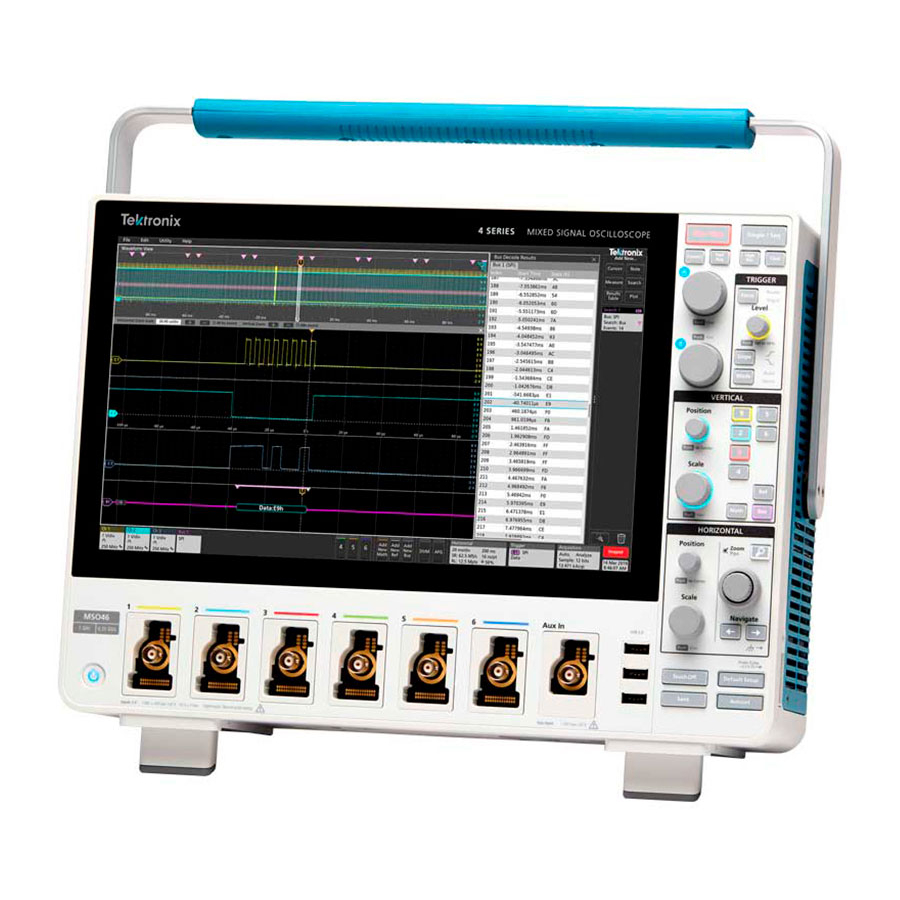
- Page 24 Getting acquainted with your instrument Figure 4: 4 Series MSO 10. Aux In auxiliary trigger input connector. A connector to which you can connect an external trigger input signal. Use the Aux In trigger signal with the Edge trigger mode.
-
Page 25: Rear Panel Connections
Getting acquainted with your instrument Rear panel connections The rear panel connections supply power to the instrument and provide connectors for network, USB devices, video, reference signals, and the AFG output. 1. LAN connector (RJ-45) connects the instrument to a 10/100/1000 Base-T local area network. 2. -
Page 26: User Interface
Getting acquainted with your instrument User interface The touch screen user interface contains waveforms and plots, measurement readouts, and touch-based controls to access all oscilloscope functions. Note: Refer to the instrument help for detailed information on using the user interface to display waveforms and take measurements. - Page 27 Getting acquainted with your instrument • The Measure button opens a configuration menu from which to select and add measurements to the Results bar. Each measurement you add has a separate badge. Double-tap a measurement badge to open its configuration menu. •...
-
Page 28: User Interface Elements
Getting acquainted with your instrument User interface elements Each area of the user interface has a specific function that helps manage information or controls. This topic shows and describes the key user interface elements. The Waveform Record View is a graphical high-level view of the overall waveform record length, how much of the record is on the screen (shown in brackets), the location of key time events including the trigger event, and the current position of waveforms cursors. - Page 29 Getting acquainted with your instrument The Zoom icon (in upper right corner of Waveform and Plot views) toggles zoom on and off. The front panel Zoom button and knobs also turn on zoom mode and change the position and horizontal size of the Zoom Box. The Trigger Level Indicator icon(s) shows the trigger level on the trigger source waveform.
-
Page 30: Badges
Getting acquainted with your instrument The markers are displayed, for about three seconds, after any Offset, Position, or Scale control change that leaves the channel dynamic range limits within the acquisition window. After about three seconds the markers become short lines at the left edge of the graticule. - Page 31 Getting acquainted with your instrument Measurement badges Measurement badges are located in the Results bar. They show measurements or search results. The badge title also shows the measurement source or sources. To add a Measurement badge, tap the Add New Measurement button and select a measurement. Double-tap a Measurement badge to open its configuration menu to change or refine settings.
- Page 32 Getting acquainted with your instrument are displayed when statistics are shown in the badge. The Pass/Fail status, number of Failures, and the Limit(s) set in the Pass/Fail Testing panel are available in the Measurement Results table. Measurement badges are listed in the order created, starting at the top of the Results bar. Deleting a Measurement badge does not change the order or names of the remaining badges.
- Page 33 Getting acquainted with your instrument To add the Waveform Histogram badge to Results bar, set the Display to On from the Result Badge menu. Double-tap a Waveform Histogram badge to open its configuration menu to change settings. The histogram badge displays the measurements which are checked in the Result Badge menu. You can drag the badge to change its position in the Results bar and open the badge right-click menu to access a quick-action menu.
- Page 34 Getting acquainted with your instrument Some searches also provide Min and Max navigation buttons that open the Zoom mode and center the waveform in the display at the minimum or maximum value for that search event in the current acquisition. Search badges are listed in the order created.
- Page 35 Unsup Accessory is unsupported. Prb Fault Critical accessory fault. Please re-attach the accessory. If the problem persists, contact Tektronix service. Over Rng The signal voltage or current is over range. Please reduce the signal amplitude. Temp The probe has experienced an over temperature condition. Please remove the probe from the high temperature area.
- Page 36 Description S-param Error during S-parameter transfer. Please reattach the probe. If the problem persists, contact Tektronix Service. History badge The History badge is shown in the Results bar. Navigate the history acquisitions by using the Previous/Next or Play/Pause buttons. Timestamp shows the time difference between the previous acquisition and the selected acquisition.
- Page 37 Getting acquainted with your instrument The Reference acquisition readout shows the timestamp when the acquisition occurred in time in history. It also displays the delta between the Selected acquisition and the Reference acquisition timestamps. There are two ways to delete the History badge. •...
-
Page 38: Configuration Menus
Getting acquainted with your instrument Action Result Example Flick Flick the badge off the bottom edge of the display to remove it from the Settings bar. Flick the badge off the right edge of the display to remove it from the Results bar. Flick from the right or bottom edge to recover a removed badge. -
Page 39: Zoom User Interface
Getting acquainted with your instrument Related settings are grouped into 'panels'. Tap the panel name to show those settings. Changes to panel settings can change the values and/or fields shown in that panel and other panels. Tap anywhere outside a configuration menu to close it. To open Help content for a configuration menu, tap the question mark icon in the upper right corner of the menu. -
Page 40: Using The Touch Screen Interface For Common Tasks
Getting acquainted with your instrument A zoom box lets you quickly draw a box around an area of interest in the Waveform or Zoom Overview. Drawing a box immediately puts the oscilloscope into zoom mode. To draw a zoom box, tap the DRAW-A-BOX button (while in Zoom mode), then touch and drag on the waveform to draw a box waveform. - Page 41 Getting acquainted with your instrument Task Touchscreen UI action Mouse action Close a configuration menu. Some Tap anywhere outside the menu or dialog. Click anywhere outside the menu or dialog. dialog boxes will not close until you click an OK, Close, or other button in the dialog.
-
Page 42: Configure The Instrument
Configure the instrument Configure the instrument Configurations to help operate your instrument efficiently. Refer to the instrument help for additional configuration information. Update your MSO with the latest firmware Ensure the instrument firmware is up to date by checking online and then installing the firmware, if needed. 1. -
Page 43: Run Signal Path Compensation (Spc)
4. Close the Calibration configuration dialog when SPC has completed. If the SPC fails, write down any error message text. Make sure that all probes and cables are disconnected and run the SPC again. If the SPC still fails, contact Tektronix Customer Support. Compensate the TPP Series probes Probe compensation adjusts the high frequency response of a probe for best waveform capture and measurement accuracy. -
Page 44: Connect To A Network (Lan)
Configure the instrument Connect a supported probe to an input channel. Connect the probe tip and ground lead of the probe to the PROBE COMP terminals. Note: Connect only one probe at a time to the PROBE COMP terminals. Turn off all channels. Turn on the channel to which the probe is connected. -
Page 45: Cleaning The Instrument
Configure the instrument 4. Tap Test Connection to verify that the network connection is working. The LAN Status icon turns green when the instrument successfully connects to your network. If you have problems connecting to your network, contact your system administration resource for help. -
Page 46: Operating Basics
Operating basics Operating basics These procedures are an introduction to using the interface to do common tasks. Refer to the instrument help for detailed information on menu and field settings. Add a channel waveform to the display Use this procedure to add a channel signal to the Waveform View. 1. -
Page 47: Configure Channel Or Waveform Settings
Operating basics Configure channel or waveform settings Use the channel and waveform configuration menus to set parameters such as vertical scale and offset, coupling, bandwidth, probe settings, deskew values, external attenuation values, and other settings. Before you begin Prerequisite: There is a channel or waveform badge in the Settings bar. Procedure 1. -
Page 48: Autoset To Quickly Display A Waveform
Operating basics Autoset to quickly display a waveform The Autoset function analyzes the signal characteristics and changes the instrument Horizontal, Vertical, and Trigger settings to automatically display a triggered waveform. You can then make further changes to trigger and horizontal settings to view the waveform point of interest. -
Page 49: Set The Acquisition Mode
Operating basics To trigger on a bus, you must first add the bus to the Waveform view. See Add a math, reference, or bus waveform on page 51 Note: Triggering on buses other than Parallel requires purchasing and installing serial trigger and analysis options. 3. -
Page 50: Set Horizontal Parameters
Operating basics 3. Tap the Help icon on the menu title for more information on these settings. 4. Tap outside the menu to close the menu. Set Horizontal parameters Use this procedure to set the horizontal time base parameters such as mode, minimum sample rate, horizontal scale, delay, and trigger delay time (relative to the center of the waveform record. -
Page 51: Add A Math, Reference, Or Bus Waveform
Operating basics Add a math, reference, or bus waveform Math waveforms let you create new waveforms based on operations between two or more waveforms or by applying equations to waveform data. A reference waveform is a static waveform record displayed for comparison. Bus waveforms let you view and analyze serial or parallel data. -
Page 52: Add A Measurement
Operating basics Add a measurement Use this procedure to select and add measurements. Acquire the channel(s) and/or waveform(s) on which you want to take measurements. Note: Waveforms do not need to be displayed to be used for measurements, as long as the channel or waveform badge is on the Settings bar and is acquiring the signal to measure. - Page 53 Operating basics Select a measurement category panel, such as Amplitude Measurements or Timing Measurements, to display measurements for those categories. Some optional measurement packages are available in this menu as well like PWR, DJA, DBDDR3, DPM, IMDA, and WBG-DPT. Select a measurement and tap Add to add the measurement to the Results bar. You can also double-tap a measurement to add it to the Results bar.
-
Page 54: Configure A Measurement
Operating basics Configure a measurement Use this procedure to add statistical readouts to the measurement badge, display plots for the measurement, and refine measurement parameters (configuration, global versus local scope of settings, gating, filtering, and so on). 1. Double-tap a measurement badge to open its Measurement configuration menu. 2. - Page 55 Operating basics 2. Tap a Plots button to add that plot for the measurement to the screen. The following shows adding a Histogram plot. You can add more than one plot to measurements (to different measurements or the same measurement). For example, you can add two histogram plots for the same measurement, set one to display the X-Axis with a Logarithmic scale, and the other plot to display the X-Axis with a Linear scale.
-
Page 56: Add A Search
Operating basics 3. You can move plot windows by dragging the Plot view title bar to a new position. The blue background area moves to show where the plot will be located when you remove your finger from the title bar. You can also resize plot windows by selecting and dragging the Plot view border. -
Page 57: Delete A Measurement Or Search Badge
Operating basics 4. To stop showing marks on a waveform, double-tap the Search badge and tap Display to Off. 5. To move the waveform to center marks on the display, push the Run/Stop front panel button to stop acquisition, single-tap a Search badge, and tap the <... -
Page 58: Change Waveform View Settings
Operating basics Change waveform view settings Use this procedure to change the waveform display mode (Stacked or Overlay), waveform trace interpolation algorithm, waveform persistence, style and intensity, and graticule style and intensity. 1. Double-tap on an open graticule area to open the Waveform View configuration menu. 2. - Page 59 Operating basics 3. Use Multipurpose Knobs A and B to move the cursors, or touch and drag a cursor. Cursors show readouts that show position and difference measurements between the cursors. 4. To move the cursors to a different channel or waveform, just tap in that waveform graticule. 5.
- Page 60 Operating basics The cursor configuration menu in an XY plot. 6. To split the cursors between two waveforms, tap the Source field and select Split and select the source for each cursor. The cursors are moved to the specified waveforms. 7.
-
Page 61: Connect The Oscilloscope To A Pc Using A Usb Cable
Operating basics Connect the oscilloscope to a PC using a USB cable Use a USB cable to connect the oscilloscope directly to a PC for remote instrument control. 1. On the oscilloscope, select Utility > I/O from the menu bar. 2. -
Page 62: Index
Index cursors menu A knob Acquisition controls acquisition menu, open Default Setup button delete a measurement badge a channel to the display display a channel a measurement badge display cursors a measurement plot documentation a search badge Draw-a-Box button (Zoom) signal to the screen DVM option waveform to the screen... - Page 63 front panel (continued) how to (continued) Single/Seq button use mouse with the UI Slope button How to Touch Off button change display mode (stacked, Overlay) Trigger USB ports Vertical Zoom button (front panel) inactive channel buttons Zoom/Pan knobs (horizontal) intensity, graticule intensity, waveform GPIB talk/listen address graticule intensity...
- Page 64 clock format (12/24 hr) GPIB talk/listen address panels, menu probe deskew persistence, waveform probe parameters pinching and handle rotate time zone plot a measurement Settings bar Plot button show a measurement Position knob Single/Seq button Position knob (horizontal) Slope button (front panel) power cord connector (rear panel) SPC (signal path compensation) power standby mode...
- Page 65 zoom icon Zoom overview Zoom title bar Zoom/Pan knobs (horizontal)
Need help?
Do you have a question about the MSO 4 Series and is the answer not in the manual?
Questions and answers