Tektronix MSO 4 Series Manual
Hide thumbs
Also See for MSO 4 Series:
- Help manual (768 pages) ,
- Installation and safety (73 pages) ,
- Quick start manual (65 pages)

Related Manuals for Tektronix MSO 4 Series


Summary of Contents for Tektronix MSO 4 Series
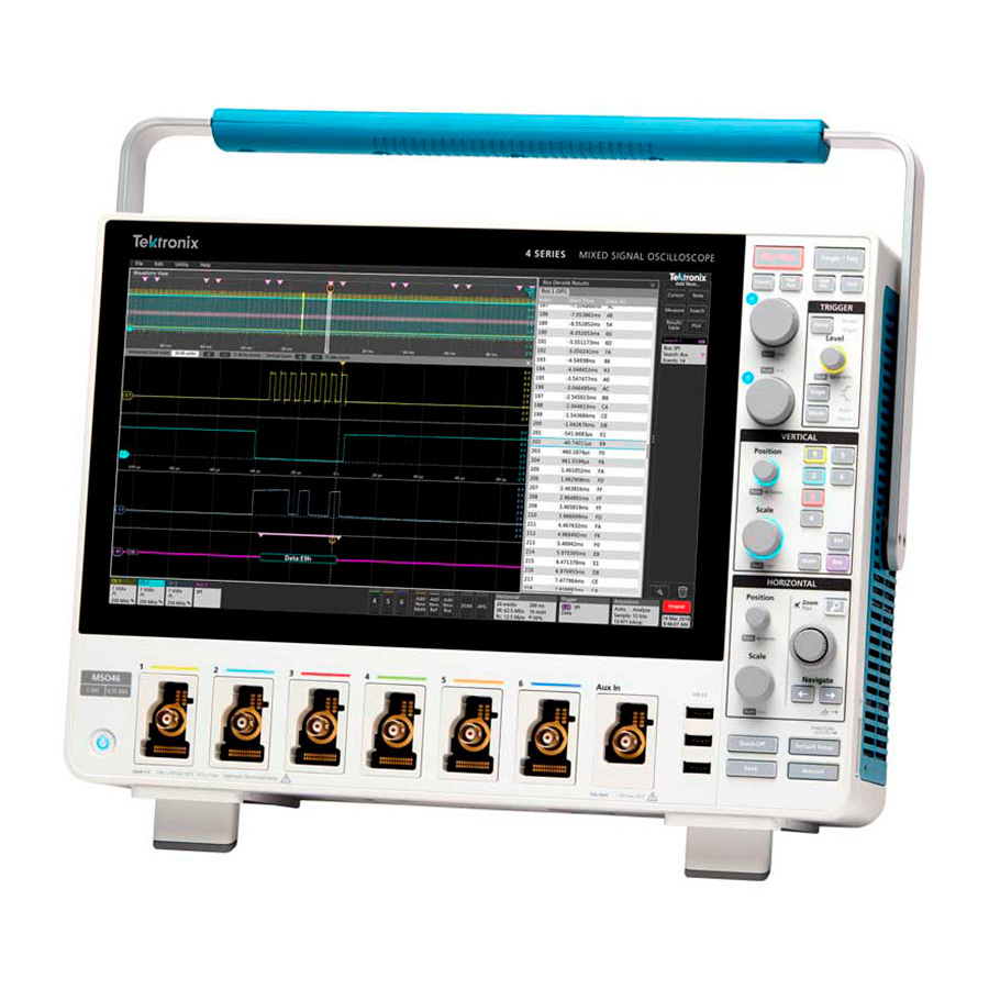
- Page 1 4 Series MSO (MSO44, MSO46) Service Register now! Click the following link to protect your product. www.tek.com/register *P 077154700* 077-1547-00...
- Page 2 Copyright © Tektronix. All rights reserved. Licensed software products are owned by Tektronix or its subsidiaries or suppliers, and are protected by national copyright laws and international treaty provisions. Tektronix products are covered by U.S. and foreign patents, issued and pending. Information in this publication supersedes that in all previously published material. Specifications and price change privileges reserved.
-
Page 3: Table Of Contents
Table of Contents Table of Contents List of Figures....................................5 List of Tables....................................6 Important safety information................................7 General safety summary................................7 Service safety summary...............................10 Terms in the manual................................10 Terms on the product................................10 Symbols on the product............................... 10 Preface......................................11 Supported products................................11 Replaceable parts................................ - Page 4 Table of Contents Using the replaceable parts list............................33 Rear case assembly with handle and feet........................... 34 Front assembly..................................36 Rear chassis assembly with power supply and fans......................38 Front assembly (Backside)..............................40 Front chassis assembly with acqusition board and processor board...................42 4 Series MSO (MSO44, MSO46) Service...
-
Page 5: List Of Figures
List of Figures List of Figures Figure 1: 4 Series MSO block diagram............................12 Figure 2: Primary troubleshooting tree............................31 Figure 3: Rear case assembly with handle and feet exploded view................... 34 Figure 4: Front assembly exploded view.............................36 Figure 5: Rear chassis assembly with power supply and fans - exploded view................38 Figure 6: Front assembly (Backside) exploded view........................40 Figure 7: Front chassis assembly with acqusition board and processor board- exploded view..........42 4 Series MSO (MSO44, MSO46) Service... -
Page 6: List Of Tables
List of Tables List of Tables Table 1: External inspection checklist............................16 Table 2: Internal inspection checklist............................17 Table 3: Required equipment for removal and replacement....................... 18 Table 4: Failure symptoms and possible causes.........................30 Table 5: Parts list column descriptions............................33 Table 6: Rear case.................................. -
Page 7: Important Safety Information
Important safety information Important safety information This manual contains information and warnings that must be followed by the user for safe operation and to keep the product in a safe condition. To safely perform service on this product, see the Service safety summary that follows the General safety summary. General safety summary Use the product only as specified. - Page 8 Important safety information Use only insulated voltage probes, test leads, and adapters supplied with the product, or indicated by Tektronix to be suitable for the product. Observe all terminal ratings To avoid fire or shock hazard, observe all rating and markings on the product. Consult the product manual for further ratings information before making connections to the product.
- Page 9 Warning: The product is heavy. Use a two-person lift or a mechanical aid. Use only the Tektronix rackmount hardware specified for this product. Probes and test leads Before connecting probes or test leads, connect the power cord from the power connector to a properly grounded power outlet.
-
Page 10: Service Safety Summary
Important safety information Risk assessment warnings and information Service safety summary The Service safety summary section contains additional information required to safely perform service on the product. Only qualified personnel should perform service procedures. Read this Service safety summary and the General safety summary before performing any service procedures. -
Page 11: Preface
Preface Preface This manual contains service information for your instrument. Read the General and Service safety summaries before servicing the product. Be sure to read the introductions to all procedures. These introductions provide important information needed to perform the service correctly, safely, and efficiently. -
Page 12: Theory Of Operation
Theory of operation Theory of operation This chapter describes the electrical operation of the oscilloscope to the module level. The block diagram shows the oscilloscope module interconnections. Figure 1: 4 Series MSO block diagram Power supply The Power Supply board converts AC line voltage to +12 V to power for all internal circuits. Processor board The processor board contains the following functions: Processor system... -
Page 13: Front Panel And Display
Theory of operation from each preamplifier goes through a digitizer, and then into acquisition memory. The analog signal from each preamplifier is also distributed to a trigger circuit. Analog Front-end All of the analog and digital inputs are routed to the analog Front-end circuitry. The analog channels are amplified and attenuated through the front-end circuitry, and are output to the acquisition ASICs. -
Page 14: Adjustment Procedures
Adjustment procedures This chapter contains information about instrument adjustment. Adjustment Adjustment and calibration can be performed only by a Tektronix Service Center. See Contacting Tektronix, following the title page in this manual, for information on contacting Tektronix Service Support. Adjustment interval The voltage and timing references inside the instrument are very stable over time and do not need routine adjustment. -
Page 15: Maintenance
Use a 75% isopropyl alcohol solution as a cleaner for cabinet parts. Before using any other type of cleaner, consult your Tektronix Service Center or representative. Inspection - Exterior. Inspect the outside of the instrument for damage, wear, and missing parts. Immediately repair defects that could cause personal injury or lead to further damage to the instrument. -
Page 16: Flat Panel Display Cleaning
Do not disassemble or clean the front chassis assembly (other than cleaning the front panel display and removing panel knobs). Disassembling the front chassis assembly requires that the instrument be returned to your nearest Tektronix Service Center for calibration. Warning: To avoid electric shock or damage to the instrument, remove instrument power. Before performing any procedure that follows, power down the instrument and disconnect it from line voltage. -
Page 17: Lubrication
• A complete description of the required service. Mark the address of the Tektronix Service Center and the return address on the shipping carton in two prominent locations. Removal and replacement procedures This section contains procedures for removal and installation of replaceable modules in the instrument. Refer to... -
Page 18: Required Equipment
Maintenance Note: Read the cleaning procedure before disassembling the instrument for cleaning. Required equipment Most assemblies in this instrument can be removed with a T-10 or T8 Torx® screwdriver tip. Table 3: Required equipment for removal and replacement Item No. Name Description Screwdriver handle... - Page 19 Maintenance 4. Use a screwdriver with T-10 Torx tip to remove the four screws from each foot assembly. 5. Remove the feet assembles. 6. To reinstall, reverse the above steps. Use a screwdriver with T-10 Torx tip to secure the eight screws. First insert and tighten the screws that are near the front edge of the instrument, then insert and tighten the screws that are near the rear edge of the instrument.
- Page 20 Maintenance 3. Remove the two couplers. 4. To reinstall, reverse the above steps. Use a screwdriver with T-10 Torx tip to secure the screws. Tighten to 0.65 N·m. Removal of the rear grill and case The following procedure describes the removal and replacement of the rear grill and case. Prerequisite: •...
- Page 21 Maintenance 2. Put fingers in handle hub holes on both side of the grill and pull the grill from the rear case. 3. Use a screwdriver with T-10 Torx tip to remove the six screws securing the rear case to the rear chassis. 4.
- Page 22 Maintenance • To prevent electrostatic damage to components whenever you work on the instrument, wear properly-grounded electrostatic prevention wrist and foot straps, and work in a tested antistatic environment on an antistatic mat. • Remove the rear grill and case. Procedure: 1.
- Page 23 Maintenance 3. Carefully lift the rear chassis off of the front chassis and disconnect the power cables, fan cables, and line filter cable. 4 Series MSO (MSO44, MSO46) Service...
- Page 24 Maintenance 4. To reinstall, reverse the above steps.Tighten the 25 screws with T-10 bit to 0.65 N·m. 5. Secure BNCs with three washers and three nuts using 9/16" socket and 2.5 N.M hand driver. Remove the power supply bracket The following procedure describes the removal and replacement of the power supply bracket. Prerequisite: •...
- Page 25 Maintenance 3. To reinstall, reverse the above steps.Tighten the 15 screws with T-10 bit to 0.65 N·m. to attach the power supply bracket to chassis with the order of the red arrow. Remove the power supply The following procedure describes the removal and replacement of the power supply. Prerequisite: •...
- Page 26 Maintenance • Remove the rear chassis assembly. Procedure: 1. Disconnect the line input cable from the power supply. 2. Use a T-10 Torx screwdriver to remove the seven screws from the power supply. 3. To reinstall, reverse the steps. Tighten the T-10 Torx screws to 0.65 N·m when reinstalling. Remove the main fan assembly The following procedure describes the removal and replacement of the power supply bracket.
- Page 27 Maintenance 2. Remove the cable ties and main fan assembly from the rear chassis. 3. To remove the fan from the bracket, carefully pull the fan from each corner of the bracket to disconnect the elastic fan attachments . 4. To reinstall, reverse the steps. Install the fan on the bracket in the correct orientation for the fan power cable (see photo). Use a needle nose plier to reinstall the fan elastic attachments on each corner.
- Page 28 Maintenance Procedure: 1. Disconnect the front panel cable from the main board as shown below. 2. Use a T-10 Torx screwdriver to remove the 23 screws that have attached the main board to the front chassis assembly . 3. To reinstall, reverse the above steps. Tighten the T-10 Torx screws to 0.65 N·m when reinstalling. Remove the processor board The following procedure describes the removal and replacement of the processor board.
- Page 29 Maintenance 2. Carefully disconnect the processor board from the main board. 3. Disconnect the display cable from the processor board as shown below. 4. To reinstall, reverse the above steps. Tighten the T-10 Torx screws to 0.65 N·m when reinstalling. 4 Series MSO (MSO44, MSO46) Service...
-
Page 30: Troubleshooting
This subsection contains information and procedures to help you determine if a faulty power supply is the problem with your instrument. If replacing the power supply does not fix the fault, you will need to return the instrument to a Tektronix Service Center for repair, as no other internal electronic assemblies or modules are user-replaceable. -
Page 31: Instrument Self Tests
Utility > Self Test. Select a test mode and run the self tests. If you continue to get errors on one or more tests, you will need to return the instrument to your nearest Tektronix Service Center for repair. -
Page 32: Software Updates
Specifications and Performance Verification manual (Tektronix part number 077-1546-XX). Download this manual from the Tektronix Web site (www.tek.com/manuals). If the instrument fails the Performance Verification tests, it must be returned to a Tektronix Service Center for adjustment. 4 Series MSO (MSO44, MSO46) Service... -
Page 33: Replaceable Parts
Instrument serial number • Instrument modification number, if applicable If you order a part that has been replaced with a different or improved part, your local Tektronix field office or representative will contact you concerning any change in part number. Module servicing Modules can be serviced by selecting one of the following three options. -
Page 34: Rear Case Assembly With Handle And Feet
Replaceable parts Column Column name Description 3 and 4 Serial number Column three indicates the serial number at which the part was first effective. Column four indicates the serial number at which the part was discontinued. No entry indicates the part is good for all serial numbers. -
Page 35: Table 6: Rear Case
Replaceable parts Table 6: Rear case Index Tektronix part Serial no. Serial no. Name & description number number effective discont'd Figure 3 on page 34 211-1688-XX SCREW, MACHINE, M3X0.5X10, FLAT HEAD 90 DEG, SUS410 NYLOK, TORX T10 050-3905-XX MODULE ASSY:SERVICE REPLACEMENT KIT, HANDLE METAL... -
Page 36: Front Assembly
Replaceable parts Front assembly Figure 4: Front assembly exploded view 4 Series MSO (MSO44, MSO46) Service... -
Page 37: Table 7: Front Assembly
Figure 4 on page 36 MODULE ASSY:SERVICE REPLACEMENT KIT;DISPLAY/TOUCH 065-1052-XX SCREEN ASSY Return the instrument to Tektronix for service. MODULE ASSY:SERVICE REPLACEMENT KIT;6CH FRONT 065-1056-XX CASE WITH LABELS MSO46 065-1055-XX MODULE ASSY:SERVICE REPLACEMENT KIT;4CH FRONT CASE WITH LABELS... -
Page 38: Rear Chassis Assembly With Power Supply And Fans
Replaceable parts Rear chassis assembly with power supply and fans Figure 5: Rear chassis assembly with power supply and fans - exploded view 4 Series MSO (MSO44, MSO46) Service... -
Page 39: Table 8: Rear Chassis Assembly With Power Supply And Fans
Replaceable parts Table 8: Rear chassis assembly with power supply and fans Fig. & Tektronix part Serial no. Serial no. Name & description index number effective discont'd number Figure 5 on page 38 BRACKET, POWER SUPPLY, 750W 407-6131-XX SHIELD, INSULATOR, POWER SUPPLY, SAFETY CONTROLLED... -
Page 40: Front Assembly (Backside)
Front assembly (Backside) Figure 6: Front assembly (Backside) exploded view Note: None of the components listed are user-replaceable. Return the instrument to your nearest Tektronix Service Center to repair or replace any internal components or assemblies in this diagram. 4 Series MSO (MSO44, MSO46) Service... -
Page 41: Table 9: Front Assembly (Backside)
Figure 6 on page 40 CASE, FRONT 202-0564-XX Return the instrument to Tektronix for service. BUTTON, POWER SWITCH, SAFETY CONTROLLED 366-0920-XX Return the instrument to Tektronix for service. MODULE ASSY, SERVICE REPLACEMENT KIT, 4CH PROBE 065-1053-XX INTERFACE WITH VPI BUCKETS Return the instrument to Tektronix for service. -
Page 42: Front Chassis Assembly With Acqusition Board And Processor Board
Figure 7: Front chassis assembly with acqusition board and processor board- exploded view Note: None of the components listed are user-replaceable. Return the instrument to your nearest Tektronix Service Center to repair or replace any internal components or assemblies in this diagram. - Page 43 CHASSIS, FRONT, ASSEMBLY 441-2901-XX Return the instrument to Tektronix for service. CIRCUIT BOARD ASSY, PROCESSOR, 878-1383-XX TESTED 878-1383-XX WITH PACKAGING Return the instrument to Tektronix for service. CIRCUIT BOARD ASSY, 6CH MAIN, 389-5345-XX, BOMBLD STD 878-1376-XX Return the instrument to Tektronix for service.
Need help?
Do you have a question about the MSO 4 Series and is the answer not in the manual?
Questions and answers