Table of Contents
Advertisement
Quick Links
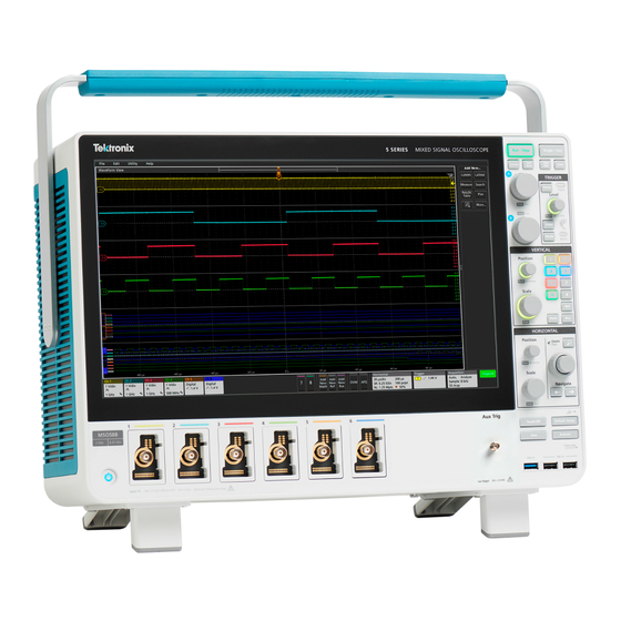
5 Series B Mixed Signal Oscilloscopes
MSO54B, MSO56B, MSO58B
Quick Start Manual
Warning: The servicing instructions are for use by qualified personnel only. To avoid personal injury, do not perform any servicing unless you are qualified
to do so. Refer to all safety summaries prior to performing service.
Supports Product Firmware Version 1.36 and above
Register now!
Click the following link to protect your product.
tek.com/register
*P077172300*
077-1723-00
June 2023
Advertisement
Table of Contents

Related Manuals for Tektronix MSO56B


Summary of Contents for Tektronix MSO56B
- Page 1 5 Series B Mixed Signal Oscilloscopes MSO54B, MSO56B, MSO58B Quick Start Manual Warning: The servicing instructions are for use by qualified personnel only. To avoid personal injury, do not perform any servicing unless you are qualified to do so. Refer to all safety summaries prior to performing service.
- Page 2 Copyright © 2023, Tektronix. 2023 All rights reserved. Licensed software products are owned by Tektronix or its subsidiaries or suppliers, and are protected by national copyright laws and international treaty provisions. Tektronix products are covered by U.S. and foreign patents, issued and pending. Information in this publication supersedes that in all previously published material. Specifications and price change privileges reserved.
-
Page 3: Warranty
Warranty Tektronix warrants that this product will be free from defects in materials and workmanship for a period of one (1) year from the date of shipment. If any such product proves defective in materials or workmanship during this warranty period, Tektronix, at its option, either will repair the defective product without charge for parts and labor, or will provide a replacement in exchange for the defective product. -
Page 4: Documentation
Documentation Documentation Review the following user documents before installing and using your instrument. These documents provide important operating information. Product documentation The following table lists the primary product specific documentation available for your product. These and other user documents are available for download from www.tek.com. -
Page 5: Table Of Contents
Run Signal Path Compensation (SPC)..........................44 Compensate the TPP Series probes........................... 44 Connect to a network (LAN)..............................45 Operating basics..................................46 Add a channel waveform to the display..........................46 Configure channel or waveform settings..........................46 5 Series B Mixed Signal Oscilloscopes MSO54B, MSO56B, MSO58B Quick Start Manual... - Page 6 Contents Autoset to quickly display a waveform..........................47 How to trigger on a signal..............................48 Set the acquisition mode..............................49 Set Horizontal parameters ..............................50 Add a math, reference, or bus waveform..........................50 Add a measurement................................51 Configure a measurement..............................53 Add a plot of a measurement...............................54 Add a Search..................................
-
Page 7: Important Safety Information
Do not connect or disconnect probes or test leads while they are connected to a voltage source. Use only insulated voltage probes, test leads, and adapters supplied with the product, or indicated by Tektronix to be suitable for the product. - Page 8 Important safety information Observe all terminal ratings To avoid fire or shock hazard, observe all rating and markings on the product. Consult the product manual for further ratings information before making connections to the product. Do not exceed the Measurement Category (CAT) rating and voltage or current rating of the lowest rated individual component of a product, probe, or accessory.
-
Page 9: Probes And Test Leads
Do not float the reference lead of this probe when using with ground-referenced oscilloscopes. The reference lead must be connected to earth potential (0 V). Floating measurement use Do not float the reference lead of this probe above the rated float voltage. 5 Series B Mixed Signal Oscilloscopes MSO54B, MSO56B, MSO58B Quick Start Manual... -
Page 10: Service Safety Summary
Important safety information Service safety summary The Service safety summary section contains additional information required to safely perform service on the product. Only qualified personnel should perform service procedures. Read this Service safety summary and the General safety summary before performing any service procedures. - Page 11 Important safety information The following symbols(s) may appear on the product. 5 Series B Mixed Signal Oscilloscopes MSO54B, MSO56B, MSO58B Quick Start Manual...
-
Page 12: Compliance Information
This section lists the EMC, safety, and environmental standards with which the instrument complies. This product is intended for use by professionals and trained personnel only; it is not designed for use in households or by children. Questions about compliance information may be directed to the following address: Tektronix, Inc. PO Box 500, MS 19-045 Beaverton, OR 97077, USA tek.com... -
Page 13: Environmental Compliance
See www.dtsc.ca.gov/ hazardouswaste/perchlorate for additional information. Transporting batteries The small lithium primary cell contained in this equipment does not exceed 1 gram of lithium metal content per cell. 5 Series B Mixed Signal Oscilloscopes MSO54B, MSO56B, MSO58B Quick Start Manual... - Page 14 Compliance information The cell type has been shown by the manufacturer to comply with the applicable requirements of the UN Manual of Tests and Criteria Part III, Sub-section 38.3. Consult your carrier to determine which lithium battery transportation requirements are applicable to your configuration, including to its re-packaging and re-labeling, prior to reshipment of the product by any mode of transport.
-
Page 15: Preface
• Power, DPM, Spectrum measurements, IMDA, and Jitter options provide additional measurement and analysis functions. See the Advanced Power Analysis, DPM Analysis, and Advanced Jitter Analysis Help topics. IMDA application is available on MSO56B and MSO58B only. 5 Series B Mixed Signal Oscilloscopes MSO54B, MSO56B, MSO58B Quick Start Manual... -
Page 16: Installing Your Instrument
Installing your instrument Check shipped accessories Make sure that you received everything you ordered. If anything is missing, contact Tektronix Customer Support. In North America, call 1-800-833-9200. Worldwide, visit www.tek.com to find contacts in your area. Check the packing list that came with your instrument to verify that you have received all standard accessories and ordered items. If you purchased factory installed options such as a Serial Bus and Triggering option, or the Power measurements option, tap Help >... -
Page 17: Operating Requirements
Digital input channels, maximum input Observe probe ratings voltage range at digital inputs TLP058; ±42 V Ref In maximum input voltage at BNC (rear panel) Aux In trigger input ±5 V 5 Series B Mixed Signal Oscilloscopes MSO54B, MSO56B, MSO58B Quick Start Manual... -
Page 18: Secure (Lock) The Instrument
Installing your instrument Secure (lock) the instrument Lock an instrument to a test bench or equipment rack to prevent property loss. Attach a standard laptop security lock to the rear panel of the instrument, to secure the instrument to a workbench, rack, or other location. Powering the instrument Use this procedure to connect the instrument to line power and power on and off the instrument. -
Page 19: Check That The Instrument Passes Power-On Self Tests
If one or more power-on self tests shows Failed: 1. Power cycle the instrument. 2. Select Utility > Self Test. If one or more power-on self tests still shows Failed, contact Tektronix Customer Support. Connecting probes to the instrument Probes connect the instrument to your device under test (DUT). Use a probe that best matches your signal measurement needs. -
Page 20: Rackmount Option Information
Installing your instrument Rackmount option information An optional rackmount kit lets you install the oscilloscope in standard equipment racks. Please refer to the product datasheet at tek.com for information on rackmount options. -
Page 21: Getting Acquainted With Your Instrument
Pushing Single/Seq turns off Run/Stop mode and takes a single acquisition. The button color indicates the acquisition status (quick green flash = single acquisition acquired; solid green = waiting for trigger event). Pushing Single/Seq again takes another single acquisition. 5 Series B Mixed Signal Oscilloscopes MSO54B, MSO56B, MSO58B Quick Start Manual... - Page 22 Getting acquainted with your instrument • High Res applies unique finite impulse response (FIR) filters based on the current sample rate. This FIR filter maintains the maximum bandwidth possible for that sample rate while rejecting aliasing. The filter removes noise from the oscilloscope amplifiers and ADC above the usable bandwidth for the selected sample rate.
- Page 23 If only one Bus waveform is displayed, pushing the button turns off the Bus waveform (removes it from Waveform view). • If two or more Bus waveforms are displayed, pushing the button cycles through selecting each Bus waveform. Horizontal controls: 5 Series B Mixed Signal Oscilloscopes MSO54B, MSO56B, MSO58B Quick Start Manual...
- Page 24 Getting acquainted with your instrument • Position moves the waveform and graticule side to side on the screen (changing the trigger point position in the waveform record). Push the knob to center the trigger event to the center graticule on the Waveform view. •...
- Page 25 10. Aux In auxiliary trigger input connector. A connector to which you can connect an external trigger input signal. Use the Aux In trigger signal with the Edge trigger mode. 5 Series B Mixed Signal Oscilloscopes MSO54B, MSO56B, MSO58B Quick Start Manual...
-
Page 26: Rear Panel Connections
Getting acquainted with your instrument Rear panel connections The rear panel connections supply power to the instrument and provide connectors for network, USB devices, video, reference signals, and the AFG output. 1. Power cord connector. Use only the power cord specified for this product and certified for the country of use. 2. -
Page 27: User Interface
The Measure button opens a configuration menu from which to select and add measurements to the Results bar. Each measurement you add has a separate badge. Double-tap a measurement badge to open its configuration menu. 5 Series B Mixed Signal Oscilloscopes MSO54B, MSO56B, MSO58B Quick Start Manual... - Page 28 Getting acquainted with your instrument • The Results Table button adds a Measurement or Bus Results table to the screen. The Measurement Results table displays all measurements present in the Results bar. The Bus Results table displays bus decode information for displayed bus waveforms. Each table is contained within its own view window, which can be moved within the display area.
-
Page 29: User Interface Elements
The Trigger Position Indicator shows where the trigger event occurred in the waveform record. The trigger icon is displayed in the waveform slice that is the trigger source. 5 Series B Mixed Signal Oscilloscopes MSO54B, MSO56B, MSO58B Quick Start Manual... - Page 30 Getting acquainted with your instrument The Zoom icon (in upper right corner of Waveform and Plot views) toggles zoom on and off. The front panel Zoom button and knobs also turn on zoom mode and change the position and horizontal size of the Zoom Box. The Trigger Level Indicator icon(s) shows the trigger level on the trigger source waveform.
-
Page 31: Badges
Measurement badges are located in the Results bar. They show measurements or search results. The badge title also shows the measurement source or sources. To add a Measurement badge, tap the button and select a measurement. 5 Series B Mixed Signal Oscilloscopes MSO54B, MSO56B, MSO58B Quick Start Manual... - Page 32 Getting acquainted with your instrument Double-tap a Measurement badge to open its configuration menu to change or refine settings. The default measurement badge readout shows the measurement's mean (μ) value. Wide Badge: Wide badge displays all the phases results in a separate column. All sub-measurements are listed in the results badge in the first column.
- Page 33 Double-tap a Mask Test badge to open its configuration menu to change or refine settings. You can drag the badge to change its position in the Results bar and open the badge right-click menu to access a quick-action menu. 5 Series B Mixed Signal Oscilloscopes MSO54B, MSO56B, MSO58B Quick Start Manual...
- Page 34 Getting acquainted with your instrument There are two ways to delete Channel and Waveform badges. • Right-click the badge and turn it off. • Flick the badge off the right edge of the display to remove it from the Results bar. Flicking left from the right edge of the Results bar recovers the badge.
- Page 35 Deletes all the Measurement (standard, power, etc.)/Search badges in the Results bar. 2. When Delete All Measurements is selected, the oscilloscope asks for the confirmation to delete all the measurements/search at a time. 5 Series B Mixed Signal Oscilloscopes MSO54B, MSO56B, MSO58B Quick Start Manual...
- Page 36 Getting acquainted with your instrument 3. The dialog box provides you a checkbox that gives the choice to bypass remaining information dialogs. • Don’t ask for remaining items: Default is unchecked. If you leave it unchecked and clear the information dialog, then the dialog will appear again for the next measurement deletion.
- Page 37 Double-tap a System badge to open its configuration menu. The Horizontal badge also has Scale buttons, shown by single-tapping the badge. Use the Horizontal Scale buttons to increase or decrease the horizontal time setting. 5 Series B Mixed Signal Oscilloscopes MSO54B, MSO56B, MSO58B Quick Start Manual...
- Page 38 Getting acquainted with your instrument Common badge actions Action Result Example Single tap Immediate access controls (Scale, Navigation). Double tap Configuration menu with access to all settings for the badge. Touch and hold Right-click menu with single tap access to common actions. Typical actions include turning off a channel and deleting a measurement or search badge.
-
Page 39: Configuration Menus
Tap anywhere outside a configuration menu to close it. To open Help content for a configuration menu, tap the question mark icon in the upper right corner of the menu. 5 Series B Mixed Signal Oscilloscopes MSO54B, MSO56B, MSO58B Quick Start Manual... -
Page 40: Zoom User Interface
Getting acquainted with your instrument Zoom user interface Use the zoom tools to magnify waveforms to view signal details. 1. The Zoom Overview shows the entire waveform record. All waveforms are shown in Overlay mode in the Zoom Overview area. Using pinch and expand gestures on the Zoom Overview waveforms changes the horizontal time base settings. -
Page 41: Using The Touch Screen Interface For Common Tasks
Click the Draw-a-Box button, draw a box around horizontally, lift from screen; repeat. the waveform area of interest. Table continued… 5 Series B Mixed Signal Oscilloscopes MSO54B, MSO56B, MSO58B Quick Start Manual... - Page 42 Getting acquainted with your instrument Task Touchscreen UI action Mouse action Quickly scroll or pan a waveform or Touch and drag in the waveform or list. Click and drag in the waveform or list. list. Close or open the Results Bar to Tap on the Results Bar Handle (three vertical Click the Results Bar Handle (three vertical dots increase the Waveform View area.
-
Page 43: Configure The Instrument
Insert the USB flash drive into any instrument USB Host port. c. The instrument detects the update firmware and opens a dialog box. Follow the on-screen instructions to install the firmware. 5 Series B Mixed Signal Oscilloscopes MSO54B, MSO56B, MSO58B Quick Start Manual... -
Page 44: Run Signal Path Compensation (Spc)
4. Close the Calibration configuration dialog when SPC has completed. If the SPC fails, write down any error message text. Make sure that all probes and cables are disconnected and run the SPC again. If the SPC still fails, contact Tektronix Customer Support. Compensate the TPP Series probes Probe compensation adjusts the high frequency response of a probe for best waveform capture and measurement accuracy. -
Page 45: Connect To A Network (Lan)
4. Tap Test Connection to verify that the network connection is working. The LAN Status icon turns green when the instrument successfully connects to your network. If you have problems connecting to your network, contact your system administration resource for help. 5 Series B Mixed Signal Oscilloscopes MSO54B, MSO56B, MSO58B Quick Start Manual... -
Page 46: Operating Basics
Operating basics Operating basics Add a channel waveform to the display Use this procedure to add a channel signal to the Waveform View. 1. Connect signal(s) to the channel input(s). 2. Tap an Inactive Channel button (in the Settings bar) of a connected channel. The selected channel is added to the Waveform View and a Channel badge is added to the Settings bar. -
Page 47: Autoset To Quickly Display A Waveform
(analog or digital) and adjusts the horizontal, vertical, and trigger settings accordingly to display a triggered waveform for that channel. The Vertical scale is adjusted in each waveform slice of all active waveforms to maximize ADC utilization. 5 Series B Mixed Signal Oscilloscopes MSO54B, MSO56B, MSO58B Quick Start Manual... -
Page 48: How To Trigger On A Signal
Operating basics When using the Overlay Display mode, the instrument adjusts the horizontal and trigger settings of the trigger source channel to display a triggered waveform for that channel. Vertical scale and position adjustments for all active channels in Overlay Display mode are controlled by the Autoset in Overlay Display Mode Optimizes selection in the Autoset panel of the User Preferences menu. -
Page 49: Set The Acquisition Mode
1. Double-tap the Acquisition badge on the Settings bar to open the Acquisition configuration menu. 2. Select the acquisition method from the Acquisition Mode list. Set any other parameters associated with the selected acquisition type. 5 Series B Mixed Signal Oscilloscopes MSO54B, MSO56B, MSO58B Quick Start Manual... -
Page 50: Set Horizontal Parameters
Operating basics 3. Tap the Help icon on the menu title for more information on these settings. 4. Tap outside the menu to close the menu. Set Horizontal parameters Use this procedure to set the horizontal time base parameters such as mode, minimum sample rate, horizontal scale, delay, and trigger delay time (relative to the center of the waveform record. -
Page 51: Add A Measurement
7. Tap outside the menu to close the menu. Add a measurement Use this procedure to select and add measurements. Acquire the channel(s) and/or waveform(s) on which you want to take measurements. 5 Series B Mixed Signal Oscilloscopes MSO54B, MSO56B, MSO58B Quick Start Manual... - Page 52 Operating basics Note: Waveforms do not need to be displayed to be used for measurements, as long as the channel or waveform badge is on the Settings bar and is acquiring the signal to measure. Tap the button to open the Add Measurements configuration menu or drag the Measure button onto a waveform in the waveform display area to automatically set the source.
-
Page 53: Configure A Measurement
Use this procedure to add statistical readouts to the measurement badge, display plots for the measurement, and refine measurement parameters (configuration, global versus local scope of settings, gating, filtering, and so on). 1. Double-tap a measurement badge to open its Measurement configuration menu. 5 Series B Mixed Signal Oscilloscopes MSO54B, MSO56B, MSO58B Quick Start Manual... -
Page 54: Add A Plot Of A Measurement
Operating basics 2. Tap Show Statistics in Badge to add statistical readouts to the measurement badge. 3. Tap available panel titles to make changes for those categories. 4. Use the available fields to refine the measurement conditions. Displayed fields depend on the measurement. Selection changes take effect immediately. - Page 55 X-Axis with a Logarithmic scale, and the other plot to display the X-Axis with a Linear scale. 5 Series B Mixed Signal Oscilloscopes MSO54B, MSO56B, MSO58B Quick Start Manual...
-
Page 56: Add A Search
Operating basics 3. You can move plot windows by dragging the Plot view title bar to a new position. The blue background area moves to show where the plot will be located when you remove your finger from the title bar. You can also resize plot windows by selecting and dragging the Plot view border. -
Page 57: Delete A Measurement Or Search Badge
Use this procedure to change the waveform display mode (Stacked or Overlay), waveform trace interpolation algorithm, waveform persistence, style and intensity, and graticule style and intensity. 1. Double-tap on an open graticule area to open the Waveform View configuration menu. 5 Series B Mixed Signal Oscilloscopes MSO54B, MSO56B, MSO58B Quick Start Manual... -
Page 58: Display And Configure Cursors
Operating basics 2. Tap the buttons in the Display Mode to toggle between Overlay and Stacked modes. 3. Use the other controls to set the waveform interpolation algorithm, waveform point persistence, style, and intensity, and graticule style and intensity. 4. Tap the Help icon on the menu title to open the Waveform View menu help topic for more information on the waveform view parameters. - Page 59 Cursor type to select the cursors to display, such as Waveform, V Bars, H Bars, and V&H Bars. The cursor configuration menu in the waveform view. 5 Series B Mixed Signal Oscilloscopes MSO54B, MSO56B, MSO58B Quick Start Manual...
- Page 60 Operating basics The cursor configuration menu in an XY plot. 6. To split the cursors between two waveforms, tap the Source field and select Split and select the source for each cursor. The cursors are moved to the specified waveforms. 7.
-
Page 61: Remote Access From A Web Browser
1. On the oscilloscope, select Utility > I/O from the menu bar. 2. Tap USB Device Port Settings. 3. Confirm that the USB Device Port control is On (default setting). 5 Series B Mixed Signal Oscilloscopes MSO54B, MSO56B, MSO58B Quick Start Manual... - Page 62 Operating basics 4. Connect a USB cable from the PC to the USB Device port on the instrument.
-
Page 63: Maintenance
Use a 75% isopropyl alcohol solution as a cleaner for cabinet parts. Before using any other type of cleaner, consult your Tektronix Service Center or representative. Inspection - Exterior. Inspect the outside of the instrument for damage, wear, and missing parts. Immediately repair defects that could cause personal injury or lead to further damage to the instrument. -
Page 64: Service The Instrument
CAUTION: To prevent getting moisture inside the instrument during external cleaning, do not spray any cleaning solutions directly onto the screen or instrument. Service the instrument For more information on troubleshooting, maintenance, and replacing parts on your instrument refer to the instrument service manual or contact a Tektronix Service Center. -
Page 65: Returning The Instrument For Service
• A complete description of the required service. Mark the address of the Tektronix Service Center and the return address on the shipping carton in two prominent locations. 5 Series B Mixed Signal Oscilloscopes MSO54B, MSO56B, MSO58B Quick Start Manual... -
Page 66: Index
Index cursors menu A knob Acquisition controls acquisition menu, open Default Setup button delete a measurement badge a channel to the display display a channel a measurement badge display cursors a measurement plot documentation a search badge Draw-a-Box button (Zoom) signal to the screen DVM option waveform to the screen... - Page 67 (12/24 hr) set GPIB talk/listen address set horizontal parameters set probe deskew 5 Series B Mixed Signal Oscilloscopes MSO54B, MSO56B, MSO58B Quick Start Manual...
- Page 68 requirements (continued) environment open acquisition menu humidity open horizontal menu power operating signal inputs altitude range temperature humidity range Results bar temperature range Results Table button operating power requirements run signal path compensation overlay mode (waveforms) Run/Stop button Save button panels, menu scale buttons, badge persistence, waveform...
- Page 69 Waveform Histogram badges Waveform View Zoom box Zoom button (front panel) zoom icon Zoom overview Zoom title bar Zoom/Pan knobs (horizontal) 5 Series B Mixed Signal Oscilloscopes MSO54B, MSO56B, MSO58B Quick Start Manual...
Need help?
Do you have a question about the MSO56B and is the answer not in the manual?
Questions and answers