Tektronix MSO 4 Series Installation And Safety
Hide thumbs
Also See for MSO 4 Series:
- Help manual (768 pages) ,
- Quick start manual (65 pages) ,
- Manual (43 pages)

Related Manuals for Tektronix MSO 4 Series


Summary of Contents for Tektronix MSO 4 Series
- Page 1 ООО "Техэнком" Контрольно-измерительные приборы и оборудование www.tehencom.com 4 Series MSO MSO44, MSO46 Installation and Safety Supports 4 Series MSO Product Firmware V1.18.XX and above. www.tek.com 071-3644-00...
- Page 2 Tektronix. All rights reserved. Licensed software products are owned by Tektronix or its subsidiaries or suppliers, and are protected by national copyright laws and international treaty provisions. Tektronix products are covered by U.S. and foreign patents, issued and pending. Information in this publication supersedes that in all previously published material. Specifications and price change privileges reserved.
- Page 3 Warranty Tektronix warrants that this product will be free from defects in materials and workmanship for a period of three (3) years from the date of shipment. If any such product proves defective during this warranty period, Tektronix, at its option, either will repair the defective product without charge for parts and labor, or will provide a replacement in exchange for the defective product.
- Page 4 ООО "Техэнком" Контрольно-измерительные приборы и оборудование www.tehencom.com...
-
Page 5: Table Of Contents
ООО "Техэнком" Контрольно-измерительные приборы и оборудование www.tehencom.com Table of Contents Important safety information ..........................General safety summary ..........................Service safety summary ..........................Terms in the manual ............................Terms on the product ............................ Symbols on the product ..........................Preface ................................Key features .............................. - Page 6 ООО "Техэнком" Контрольно-измерительные приборы и оборудование www.tehencom.com Table of Contents Compensate the TPP Series probes ......................Connect to a network (LAN) ......................... Cleaning ............................... Operating basics Add a channel waveform to the display ....................... Configure channel or waveform settings ...................... Quickly display a waveform (Autoset) ......................
-
Page 7: Important Safety Information
Connect and disconnect properly. Do not connect or disconnect probes or test leads while they are connected to a voltage source. Use only insulated voltage probes, test leads, and adapters supplied with the product, or indicated by Tektronix to be suitable for the product. - Page 8 Be sure your work area meets applicable ergonomic standards. Consult with an ergonomics professional to avoid stress injuries. Use care when lifting and carrying the product. This product is provided with a handle for lifting and carrying. Use only the Tektronix rackmount hardware specified for this product. Probes and test leads Before connecting probes or test leads, connect the power cord from the power connector to a properly grounded power outlet.
-
Page 9: Service Safety Summary
ООО "Техэнком" Контрольно-измерительные приборы и оборудование www.tehencom.com Important safety information Beware of high voltages. Understand the voltage ratings for the probe you are using and do not exceed those ratings. Two ratings are important to know and understand: The maximum measurement voltage from the probe tip to the probe reference lead ■... -
Page 10: Terms In The Manual
ООО "Техэнком" Контрольно-измерительные приборы и оборудование www.tehencom.com Important safety information Terms in the manual These terms may appear in this manual: WARNING. Warning statements identify conditions or practices that could result in injury or loss of life. CAUTION. Caution statements identify conditions or practices that could result in damage to this product or other property. Terms on the product These terms may appear on the product: DANGER indicates an injury hazard immediately accessible as you read the marking. -
Page 11: Preface
ООО "Техэнком" Контрольно-измерительные приборы и оборудование www.tehencom.com Preface This manual provides product safety and compliance information, describes how to connect and power on the oscilloscope, and introduces the instrument features, controls and basic operations. See the product Help file for more detailed information. Key features Welcome to the 4 Series MSO. -
Page 12: Related Documents
To learn about Use this document How to use instrument 4 Series MSO (MSO44, MSO46) Installation and Safety Manual (This document, Tektronix part functions number 071-3644-xx); standard accessory with the instrument. Single document with English, Japanese, and Simplified Chinese languages. A Russian language version is available to download from the Tektronix web site (Tektronix part number 077-1511-xx) 4/5/6 Series MSO Help (Tektronix part number 077-1303-xx;... -
Page 13: Installing Your Instrument
Installing your instrument Check shipped accessories Make sure that you received everything you ordered. If anything is missing, contact Tektronix Customer Support. In North America, call 1-800-833-9200. Worldwide, visit www.tek.com to find contacts in your area. Check the packing list that came with your instrument to verify that you have received all standard accessories and ordered items. -
Page 14: Operating Requirements
ООО "Техэнком" Контрольно-измерительные приборы и оборудование www.tehencom.com Installing your instrument Operating requirements Use the oscilloscope within the required operating temperature, power, altitude, and signal input voltage ranges to provide the most accurate measurements and safe instrument operation. Environment requirements Characteristic Description Operating temperature 0 °C to +50 °C (+32 °F to +122 °F) -
Page 15: Input Signal Requirements
ООО "Техэнком" Контрольно-измерительные приборы и оборудование www.tehencom.com Installing your instrument Input signal requirements Keep the input signals within allowed limits to ensure the most accurate measurements and prevent damage to the analog and digital probes or instrument. Make sure that input signals are within the following requirements. Input Description Analog input channels, 1 M Ω... -
Page 16: Powering The Oscilloscope
ООО "Техэнком" Контрольно-измерительные приборы и оборудование www.tehencom.com Installing your instrument Powering the oscilloscope Use this procedure to connect the oscilloscope to line power and power on and off the oscilloscope. Always connect the oscilloscope to AC power using the power cord that shipped with the instrument. Prerequisite: Use the AC power cord that shipped with your oscilloscope. -
Page 17: Check That Oscilloscope Passes Power-On Self Tests
If one or more power-on self tests shows Failed: Power cycle the oscilloscope. Tap Utility > Self Test. If one or more power-on self tests still shows Failed, contact Tektronix Customer Support. Connecting Probes Probes and cables connect the oscilloscope to your device under test (DUT). Use a probe that best matches your signal measurement needs. -
Page 18: Rackmount Option Information
An optional rackmount kit lets you install the oscilloscope in standard equipment racks. The rackmount kit requires seven rack units (7U) of space to install. Contact Tektronix Customer Support to purchase the RM4 rackmount kit option. Follow the instructions that come with the rackmount kit (RM4 Rackmount Kit Instructions, Tektronix part number 071-3645-xx). -
Page 19: Getting Acquainted With Your Instrument
ООО "Техэнком" Контрольно-измерительные приборы и оборудование www.tehencom.com Getting acquainted with your instrument The following content provides a high-level description of the instrument controls and user interface. Refer to the instrument help for detailed information on using the controls and user interface to display waveforms and take measurements. - Page 20 ООО "Техэнком" Контрольно-измерительные приборы и оборудование www.tehencom.com Getting acquainted with your instrument ■ Run/Stop starts and stops waveform acquisition. The button color indicates the acquisition status (green = running and acquiring; red = stopped). When stopped, the oscilloscope shows waveforms from the last completed acquisition. The Run/Stop button on the screen also shows the acquisition status.
- Page 21 ООО "Техэнком" Контрольно-измерительные приборы и оборудование www.tehencom.com Getting acquainted with your instrument Push a Multipurpose knob to enable the Fine mode for making smaller increment changes. Push the knob again to exit Fine mode. Trigger controls: ■ Force forces a trigger event at a random point in the waveform and captures the acquisition. ■...
- Page 22 ООО "Техэнком" Контрольно-измерительные приборы и оборудование www.tehencom.com Getting acquainted with your instrument Vertical controls: ■ Position moves the selected waveform (Channel, Math, Reference, Bus) and its graticule up or down on the screen. The color of the Position knob indicates which waveform the knob is controlling. Push the knob to set the threshold level to 50% of the peak-to-peak amplitude range of the signal.
- Page 23 ООО "Техэнком" Контрольно-измерительные приборы и оборудование www.tehencom.com Getting acquainted with your instrument Horizontal controls: Position moves the waveform and graticule side to side on the screen (changing the trigger point position in the ■ waveform record). Push the knob to center the trigger event to the center graticule on the Waveform view. ■...
- Page 24 ООО "Техэнком" Контрольно-измерительные приборы и оборудование www.tehencom.com Getting acquainted with your instrument Miscellaneous controls: ■ Touch Off turns touch screen capability off. The Touch Off button is lighted when the touch screen is turned off. ■ Save is a one-push save operation that uses the current File > Save As settings to save screen shots (including open menus and dialog boxes), waveform files, instrument settings, and so on, as follows: ■...
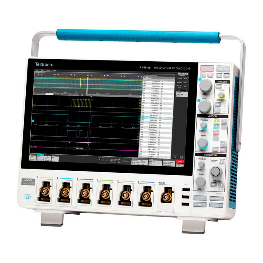
- Page 25 ООО "Техэнком" Контрольно-измерительные приборы и оборудование www.tehencom.com Getting acquainted with your instrument FlexChannel probe connectors: Figure 4: 4 Series MSO ■ FlexChannel connectors support all TekVPI+ and TekVPI measurement probes, BNC passive probes, the TPL058 FlexChannel Logic Probe, and BNC cables. You connect most probes simply by pushing them into the connector until the probe seats with a click.
-
Page 26: Rear Panel Connections
ООО "Техэнком" Контрольно-измерительные приборы и оборудование www.tehencom.com Getting acquainted with your instrument Rear panel connections The rear panel connections supply power to the oscilloscope and provide connectors for network, USB devices, video, reference signals, and the AFG output. Figure 5: 4 Series MSO 4 Series MSO LAN connector (RJ-45) connects the oscilloscope to a 10/100/1000 Base-T local area network. -
Page 27: The User Interface Screen
ООО "Техэнком" Контрольно-измерительные приборы и оборудование www.tehencom.com Getting acquainted with your instrument The user interface screen The touch screen user interface contains waveforms and plots, measurement readouts, and touch-based controls to access all oscilloscope functions. The Menu bar provides menus for typical operations including: ■... -
Page 28: The User Interface Elements
ООО "Техэнком" Контрольно-измерительные приборы и оборудование www.tehencom.com Getting acquainted with your instrument The Results Bar contains controls for displaying cursors, adding notes, plots, and result tables to the screen, and add measurements to the Results bar. The controls are: The Cursors button displays on-screen cursors in the selected view. Touch and drag, or use the Multipurpose knobs, ■... - Page 29 ООО "Техэнком" Контрольно-измерительные приборы и оборудование www.tehencom.com Getting acquainted with your instrument The Waveform Record View is a graphical high-level view of the overall waveform record length, how much of the record is on the screen (shown in brackets), the location of key time events including the trigger event, and the current position of waveforms cursors.
- Page 30 ООО "Техэнком" Контрольно-измерительные приборы и оборудование www.tehencom.com Getting acquainted with your instrument When in Zoom mode, the Waveform Record View is replaced with the Zoom Overview. See The Zoom user interface on page 27. elements The Expansion Point icon on the waveform view shows the center point around which the waveform expands and compresses when changing horizontal settings.
- Page 31 ООО "Техэнком" Контрольно-измерительные приборы и оборудование www.tehencom.com Getting acquainted with your instrument 11. The Waveform Handles on each waveform identify the source of that waveform (Cx for channels, Mx for Math waveforms, Rx for Reference waveforms, Bx for bus waveforms). The waveform handles are at the zero-volt level of the waveform by default.
-
Page 32: Badges
ООО "Техэнком" Контрольно-измерительные приборы и оборудование www.tehencom.com Getting acquainted with your instrument Badges Badges are rectangular icons that show waveform, measurement, and instrument settings or readouts. Badges also provide fast access to configuration menus. The badge types are Channel, Waveform, Measurement, Search, and System. Channel and Waveform badges Channel and Waveform (Math, Ref, Bus, Trend) badges are shown in the Settings Bar, located along the bottom left of the screen. - Page 33 ООО "Техэнком" Контрольно-измерительные приборы и оборудование www.tehencom.com Getting acquainted with your instrument Double-tap a Measurement badge to open its configuration menu to change or refine settings. The default measurement badge readout shows the measurement's mean (μ) value. Some measurements and their badges are only available as options. For example, Power measurements are only listed in the Add New Measurement menu if the 4-PWR option is installed.
- Page 34 ООО "Техэнком" Контрольно-измерительные приборы и оборудование www.tehencom.com Getting acquainted with your instrument Search badges Search badges are also shown in the Results Bar, below the Measurement badges. A search badge lists the search source, search type, and the number of search event occurrences in the current acquisition. The instrument marks the waveform where those events occur with small down-pointing triangles along the top of the waveform graticule.
- Page 35 Unable to read probe ROM. Please re-attach the accessory. Unsup Accessory is unsupported. Prb Fault Critical accessory fault. Please re-attach the accessory. If the problem persists, contact Tektronix service. Over Rng The signal voltage or current is over range. Please reduce the signal amplitude. Temp The probe has experienced an over temperature condition.
- Page 36 ООО "Техэнком" Контрольно-измерительные приборы и оборудование www.tehencom.com Getting acquainted with your instrument Error message Description No Tip No probe tip detected. Please install a compatible probe tip. Tip Fault The probe tip has a fault. Please remove and replace the probe tip. System badges System badges (in the Settings bar) display the main Horizontal, Trigger, and Acquisition settings.
- Page 37 ООО "Техэнком" Контрольно-измерительные приборы и оборудование www.tehencom.com Getting acquainted with your instrument Common badge actions Action Result Example Single tap Immediate access controls (Scale, Navigation). Double tap Configuration menu with access to all settings for the badge. Badge selection status The appearance of a badge indicates its selection status (selected or unselected), or if a measurement needs to be deleted to close a channel or waveform badge.
-
Page 38: Configuration Menus
ООО "Техэнком" Контрольно-измерительные приборы и оборудование www.tehencom.com Getting acquainted with your instrument Badge type Selected Unselected Turned off or in use Channel or Waveform Measurement Configuration menus Configuration menus let you quickly set the parameters for channels, system settings (Horizontal, Trigger, Acquisition), measurements, cursor readouts, Waveform and Plot views, note text, and so on. -
Page 39: The Zoom User Interface Elements
ООО "Техэнком" Контрольно-измерительные приборы и оборудование www.tehencom.com Getting acquainted with your instrument Tap anywhere outside a configuration menu to close it. To open Help content for a configuration menu, tap the question mark icon in the upper right corner of the menu. The Zoom user interface elements Use the zoom tools to magnify waveforms to view signal details. -
Page 40: Using The Touch Screen Interface For Common Tasks
ООО "Техэнком" Контрольно-измерительные приборы и оборудование www.tehencom.com Getting acquainted with your instrument The Zoom View shows the zoomed waveforms, as marked by the Zoom Box, in the Zoom Waveform Record View. Use pinch and/or drag options in the zoom view to change the zoomed area of interest. NOTE. - Page 41 ООО "Техэнком" Контрольно-измерительные приборы и оборудование www.tehencom.com Getting acquainted with your instrument Task Touchscreen UI action Mouse action Move a note Touch and hold on a note and quickly Click and hold the right mouse button on start to drag, then move to new position. the note and quickly start to drag, then move to the new position.
- Page 42 ООО "Техэнком" Контрольно-измерительные приборы и оборудование www.tehencom.com Getting acquainted with your instrument MSO44, MSO46 Installation and Safety Manual...
-
Page 43: Configure The Instrument
ООО "Техэнком" Контрольно-измерительные приборы и оборудование www.tehencom.com Configure the instrument Set the time zone and clock readout format Set the time zone to your region so that saved files are marked with the correct date and time information. You can also set the time format (12 or 24 hour clock). -
Page 44: Run Signal Path Compensation (Spc)
Close the Calibration configuration dialog when SPC has completed. If the SPC fails, write down any error message text. Make sure that all probes and cables are disconnected and run the SPC again. If the SPC still fails, contact Tektronix Customer Support. Compensate the TPP Series probes Probe compensation adjusts the high frequency response of a probe for best waveform capture and measurement accuracy. - Page 45 ООО "Техэнком" Контрольно-измерительные приборы и оборудование www.tehencom.com Configure the instrument Prerequisite: The oscilloscope must be powered on for at least 20 minutes before compensating a probe. Connect a supported probe to an input channel. Connect the probe tip and ground lead of the probe to the PROBE COMP terminals on the lower right of the oscilloscope (see following image).
-
Page 46: Connect To A Network (Lan)
ООО "Техэнком" Контрольно-измерительные приборы и оборудование www.tehencom.com Configure the instrument Connect to a network (LAN) Connecting to a network allows you to remotely access the instrument. Work with your network administrator to obtain the required information to connect to your network (IP address, Gateway IP address, Subnet Mask, DNS IP address, and so on). -
Page 47: Operating Basics
ООО "Техэнком" Контрольно-измерительные приборы и оборудование www.tehencom.com Operating basics These procedures are an introduction to using the interface to do common tasks. See the Help information in the application for detailed information on menu and field settings. Add a channel waveform to the display Use this procedure to add a channel signal to the Waveform View. -
Page 48: Configure Channel Or Waveform Settings
ООО "Техэнком" Контрольно-измерительные приборы и оборудование www.tehencom.com Operating basics Configure channel or waveform settings Use the channel and waveform configuration menus to set parameters such as vertical scale and offset, coupling, bandwidth, probe settings, deskew values, external attenuation values, and other settings. Prerequisite: There is a channel or waveform badge in the Settings bar. -
Page 49: Quickly Display A Waveform (Autoset)
ООО "Техэнком" Контрольно-измерительные приборы и оборудование www.tehencom.com Operating basics Tap the Other panel to set probe deskew, external attenuation, and alternate units parameters. Tap the Help icon on the menu title to open the help topic for more information. Tap outside the menu to close the menu. Quickly display a waveform (Autoset) The Autoset function analyzes the signal characteristics and changes the instrument Horizontal, Vertical, and Trigger settings to automatically display a triggered waveform. -
Page 50: How To Trigger On A Signal
NOTE. Triggering on buses other than Parallel requires purchasing and installing serial trigger and analysis options. See the Tektronix Web site for available serial trigger and analysis options. Select the other fields and panels to refine the trigger conditions. The menu fields and trigger graphic update as you make changes to the trigger settings. -
Page 51: Set The Acquisition Mode
ООО "Техэнком" Контрольно-измерительные приборы и оборудование www.tehencom.com Operating basics Tap the Help icon on the menu title for more information on these settings. Tap outside the menu to close the menu. Set the acquisition mode Use this procedure to set the method the instrument uses to acquire and display the signal. Double-tap the Acquisition badge on the Settings bar to open the Acquisition configuration menu. -
Page 52: Set Horizontal Parameters
ООО "Техэнком" Контрольно-измерительные приборы и оборудование www.tehencom.com Operating basics Tap the Help icon on the menu title for more information on these settings. Tap outside the menu to close the menu. Set Horizontal parameters Use this procedure to set the horizontal time base parameters such as mode, minimum sample rate, horizontal scale, delay, and trigger delay time (relative to the center of the waveform record. - Page 53 ООО "Техэнком" Контрольно-измерительные приборы и оборудование www.tehencom.com Operating basics Use the configuration menus to refine the waveform parameters. Displayed fields depend on the waveform and selections made in the menu. Selection changes take effect immediately. This example shows adding a Math waveform, using the Math Source fields to select Ch 1 and Ch 2 as the waveform sources, set the math type to Basic math operation, and subtracting channel 2 from channel 1.
-
Page 54: Add A Measurement
ООО "Техэнком" Контрольно-измерительные приборы и оборудование www.tehencom.com Operating basics Add a measurement Use this procedure to select and add measurements. Acquire the channel(s) and/or waveform(s) on which you want to take measurements. NOTE. Waveforms do not need to be displayed to be used for measurements, as long as the channel or waveform badge is on the Settings bar and is acquiring the signal to measure. - Page 55 ООО "Техэнком" Контрольно-измерительные приборы и оборудование www.tehencom.com Operating basics Select and add other measurements for the current source. Tap the measurement category panels to display and select other measurements to add. To add measurements for other sources, select a different source, select a measurement, and add the measurement. Tap outside the Add Measurements menu to close the menu.
-
Page 56: Configure A Measurement
ООО "Техэнком" Контрольно-измерительные приборы и оборудование www.tehencom.com Operating basics Configure a measurement Use this procedure to add statistical readouts to the measurement badge, display plots for the measurement, and refine measurement parameters (configuration, global versus local scope of settings, gating, filtering, and so on). Double-tap a measurement badge to open its Measurement configuration menu. -
Page 57: Add A Plot Of A Measurement
ООО "Техэнком" Контрольно-измерительные приборы и оборудование www.tehencom.com Operating basics Add a plot of a measurement Measurement plots let you graph the distribution of waveform data point occurrences (histogram), plot the frequency components (spectrum) of a waveform, show the time trend of a measurement, and other supported plots. Available plots depend on the measurement. - Page 58 ООО "Техэнком" Контрольно-измерительные приборы и оборудование www.tehencom.com Operating basics You can add more than one plot to measurements (to different measurements or the same measurement). For example, you can add two histogram plots for the same measurement, set one to display the X-Axis with a Logarithmic scale, and the other plot to display the X-Axis with a Linear scale.
-
Page 59: Add A Search
ООО "Техэнком" Контрольно-измерительные приборы и оборудование www.tehencom.com Operating basics Add a Search Use this procedure to set search criteria and mark a waveform where those events occur. You can search on analog and digital signals, math waveforms, and reference waveforms. You can add searches to different waveforms and multiple searches to the same waveform. -
Page 60: Delete A Measurement Or Search Badge
ООО "Техэнком" Контрольно-измерительные приборы и оборудование www.tehencom.com Operating basics NOTE. Navigation buttons are only functional when the oscilloscope acquisition mode is set to Stop. This opens the Zoom mode and moves the waveform to the previous or next event mark on the waveform. If available for a search, tap the Min or Max button to center the waveform in the display at the minimum or maximum value of the search events in the waveform record. -
Page 61: Change Waveform View Settings
ООО "Техэнком" Контрольно-измерительные приборы и оборудование www.tehencom.com Operating basics Change waveform view settings Use this procedure to change the waveform display mode (Stacked or Overlay), waveform trace interpolation algorithm, waveform persistence, style and intensity, and graticule style and intensity. Double-tap on an open graticule area to open the Waveform View configuration menu. Tap the buttons in the Display Mode to toggle between Overlay and Stacked modes. - Page 62 ООО "Техэнком" Контрольно-измерительные приборы и оборудование www.tehencom.com Operating basics Use Multipurpose Knobs A and B to move the cursors, or touch and drag a cursor. Cursors show readouts that show position and difference measurements between the cursors. To move the cursors to a different channel or waveform, just tap in that waveform graticule. To further configure cursors, double-tap on either cursor line or the cursor readouts to open the Cursors configuration menu.
-
Page 63: Connect The Oscilloscope To A Pc Using A Usb Cable
ООО "Техэнком" Контрольно-измерительные приборы и оборудование www.tehencom.com Operating basics The cursors are moved to the specified waveforms. Tap the Help icon on the menu title for more information on the menu settings. To stop showing cursors, push the front panel Cursor button, press and hold to open the right-click menu and turn cursors off, or open the Cursors configuration menu and set Display to Off. - Page 64 ООО "Техэнком" Контрольно-измерительные приборы и оборудование www.tehencom.com Operating basics MSO44, MSO46 Installation and Safety Manual...
-
Page 65: Emc, Safety And Environmental Compliance
This product is intended for use by professionals and trained personnel only; it is not designed for use in households or by children. Questions about the following compliance information may be directed to the following address: Tektronix, Inc. PO Box 500, MS 19-045 Beaverton, OR 97077, USA www.tek.com... -
Page 66: Safety Compliance
ООО "Техэнком" Контрольно-измерительные приборы и оборудование www.tehencom.com EMC, safety and environmental compliance EMC Compliance Meets the intent of Directive 2014/30/EU for Electromagnetic Compatibility when it is used with the product(s) stated in the specifications table. Refer to the EMC specification published for the stated products. May not meet the intent of the directive if used with other products. -
Page 67: Environmental Compliance
ООО "Техэнком" Контрольно-измерительные приборы и оборудование www.tehencom.com EMC, safety and environmental compliance Safety class Class I -- grounded product. Pollution degree description A measure of the contaminants that could occur in the environment around and within a product. Typically the internal environment inside a product is considered to be the same as the external. - Page 68 This symbol indicates that this product complies with the applicable European Union requirements according to Directives 2012/19/EU and 2006/66/EC on waste electrical and electronic equipment (WEEE) and batteries. For information about recycling options, check the Tektronix Web site (www.tek.com/productrecycling). Battery recycling This product contains a small installed lithium metal button cell.
- Page 69 ООО "Техэнком" Контрольно-измерительные приборы и оборудование www.tehencom.com Index Clear button, 7 clipping message, 20, 22–25 A knob, 7 clock format (12/24 hr), how to set, 31 Acquisition controls, 7 common touchscreen UI tasks, 28 acquisition menu, open, 39 compensate TPP series probes, 32 configuration menus, 26 a channel to the display, 35 configure a measurement, 44...
- Page 70 ООО "Техэнком" Контрольно-измерительные приборы и оборудование www.tehencom.com Index Autoset button, 7 handles, analog and digital, 16 Aux In, 7 High Res button, 7 Aux Trig, 7 Horizontal controls, 7 Bus button (front panel), 7 horizontal menu, open, 40 Channel buttons (front panel), 7 how to Clear button, 7 add a measurement, 42...
- Page 71 ООО "Техэнком" Контрольно-измерительные приборы и оборудование www.tehencom.com Index How to Note button, 15 change display mode (stacked, Overlay), 49 open acquisition menu, 39 inactive channel buttons, 16 open horizontal menu, 40 input signal level requirements, 3 operating intensity, graticule, 49 altitude range, 2 intensity, waveform, 49 humidity range, 2...
- Page 72 ООО "Техэнком" Контрольно-измерительные приборы и оборудование www.tehencom.com Index Ethernet port (RJ-45), 14 signal input levels, 3 LAN port (RJ-45), 14 Single/Seq button, 7 power cord, 14 Slope button (front panel), 7 security cable lock, 14 SPC (signal path compensation), 32 USB Device port, 14 stacked mode (waveforms), 49 USB Host ports, 14...
- Page 73 ООО "Техэнком" Контрольно-измерительные приборы и оборудование www.tehencom.com Index zoom icon, 16 Zoom overview, 27 Zoom title bar, 27 Zoom box, 27 Zoom/Pan knobs (horizontal), 7 Zoom button (front panel), 7 MSO44, MSO46 Installation and Safety Manual...
Need help?
Do you have a question about the MSO 4 Series and is the answer not in the manual?
Questions and answers