Table of Contents
Advertisement
Quick Links
One Technology Way • P.O. Box 9106 • Norwood, MA 02062-9106, U.S.A. • Tel: 781.329.4700 • Fax: 781.461.3113 • www.analog.com
Evaluating the ADN4612, 11.3 Gbps, 12 × 12 Digital Crosspoint Switch
FEATURES
Full featured evaluation board for the
2
USB to I
C control interface
On-board power distribution network
EVALUATION KIT CONTENTS
ADN4612
evaluation board
USB cable
DC-to-DC converter power cable
DOCUMENTS NEEDED
ADN4612
data sheet
ADN4612-EVALZ
user guide
ADN4612
evaluation board schematic
SOFTWARE NEEDED
ADN4612
evaluation software
EQUIPMENT NEEDED
A differential oscilloscope or serial data analyzer with
greater than 12 GHz analog input bandwidth
A differential pattern generator
A PC with Windows® 2000/XP
GENERAL DESCRIPTION
The
ADN4612
evaluation board user guide describes the setup
and general usage of the
ADN4612
in this document is a quick start guide, hardware configuration
instructions, and software installation instructions.
The
ADN4612
evaluation board provides access to all 12
differential input ports and 12 differential output ports of the
ADN4612
via top launch SMA connectors. Each input and output
pair is ac-coupled using a 0.1 μF capacitor.
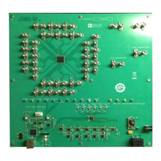
The evaluation board example (see Figure 1) is shown fully
populated with SMA connectors. The board is shipped with
only eight installed SMA connectors. The SMA connectors can
be moved to any of the 48 locations on the board by unscrewing
PLEASE SEE THE LAST PAGE FOR AN IMPORTANT
WARNING AND LEGAL TERMS AND CONDITIONS.
ADN4612
evaluation board. Included
Rev. A | Page 1 of 15
ADN4612-EVALZ User Guide
EVALUATION BOARD CONNECTION DIAGRAM
Figure 1.
ADN4612
and then reattaching the connectors to the desired locations.
The customer can purchase an additional 40 SMA connectors
from several different sources and attach the connectors for a
fully populated board. The Bill of Materials section in this user
guide provides the SMA connector part number, which is
Molex 73251-1851 or equivalent.
All microstrip (top layer) transmission lines use an RoHs-
compliant, Megtron-6 dielectric. The differential transmission
line pairs are 10 mil wide with 7.5 mil spacing and are designed to
have a differential characteristic impedance of 100 Ω. The stripline
(middle layers) transmission lines are RoHs-compliant, FR-4
material.
UG-740
Evaluation Board
Advertisement
Table of Contents

Related Manuals for Analog Devices ADN4612-EVALZ


Summary of Contents for Analog Devices ADN4612-EVALZ
-
Page 1: Features
ADN4612-EVALZ User Guide UG-740 One Technology Way • P.O. Box 9106 • Norwood, MA 02062-9106, U.S.A. • Tel: 781.329.4700 • Fax: 781.461.3113 • www.analog.com Evaluating the ADN4612, 11.3 Gbps, 12 × 12 Digital Crosspoint Switch FEATURES EVALUATION BOARD CONNECTION DIAGRAM... -
Page 2: Table Of Contents
UG-740 ADN4612-EVALZ User Guide TABLE OF CONTENTS Features ....................1 Input Signals...................4 Evaluation Kit Contents ..............1 Output Signals ................4 Documents Needed ................1 USB to I C MCU ................5 Software Needed ................1 Switches ..................5... -
Page 3: Quick Start Guide
ADN4612-EVALZ User Guide UG-740 QUICK START GUIDE This section provides a quick start procedure for using the Extract the contents of the compressed ADN4612 ADN4612 on the evaluation board. The following procedure Evaluation Software .zip file to a folder on the PC. -
Page 4: Evaluation Board Hardware
(LVPECL). Ceramic capacitors provide the ac coupling switch enables or disables power to the board. A switch regulator path to the signal input. To match with the 50 Ω transmission provides 12 V to 5 V dc-to-dc conversion. Analog Devices, Inc., line, the ADN4612 has on-chip, 50 Ω... -
Page 5: Usb To I 2 C Mcu
ADN4612-EVALZ User Guide UG-740 USB TO I C MCU SWITCHES The PIC microcontroller unit (MCU)-based USB device Table 2 lists the manual push-button switches available on the communication circuit allows device register read or write ADN4612 evaluation board and the function each switch controls. -
Page 6: Evaluation Board Software
UG-740 ADN4612-EVALZ User Guide EVALUATION BOARD SOFTWARE SOFTWARE OVERVIEW Some operating systems require placing the hsiUsb.dll file into the folder above the ADN4612_0vX.exe file to operate the software. The software requires the hsiUsb.dll file to establish successful communication with the device. The file is located in the same folder as the ADN4612_0vX.exe executable. - Page 7 ADN4612-EVALZ User Guide UG-740 Input Controls ADDRESS RX EN The ADDRESS box is the register address field. Values are hexadecimal and only values 00 to FF are valid; the register Select the EN check boxes to enable or disable the inputs. By address field does not recognize 0x as a valid value.
- Page 8 UG-740 ADN4612-EVALZ User Guide Script Control Import Register File Export Register File The import register file imports the register content of the ADN4612 register map from a text file. The function restores The export register file exports the register content of the the GUI to the register settings in the import file.
-
Page 9: Load From Eeprom Procedure
ADN4612-EVALZ User Guide UG-740 Figure 5. Load EEPROM Memory Control Software Screenshot LOAD FROM EEPROM PROCEDURE The LOAD ADN4612 button is enabled after the load is complete. To enable the power-on ready operation and alleviate system Click the Device Address drop-down menu to select the... -
Page 10: Evaluation Board Schematics And Artwork
UG-740 ADN4612-EVALZ User Guide EVALUATION BOARD SCHEMATICS AND ARTWORK Figure 6. ADN4612 Evaluation Board Power Distribution Network Schematic Rev. A | Page 10 of 15... - Page 11 ADN4612-EVALZ User Guide UG-740 Figure 7. ADN4612 Design Schematic Rev. A | Page 11 of 15...
- Page 12 UG-740 ADN4612-EVALZ User Guide Figure 8. ADN4612 Evaluation Board Digital Control Block Schematic Rev. A | Page 12 of 15...
-
Page 13: Ordering Information
ADN4612-EVALZ User Guide UG-740 ORDERING INFORMATION BILL OF MATERIALS Table 4. Item Reference Designator Description Manufacturer Part Number ADN4612-EVALZ Printed circuit board Analog Devices ADN4612-EVALZ +5 V, +12 V, PIC_VDD Connector-PCB, test points, grey Components TP104-01-08 Corporation C1 to C14, C17 to C30,... - Page 14 ADP1706ARDZ-3.3-R7 CMOS, linear regulator U15 to U18 Analog Devices IC, high voltage, Analog Devices AD8215YRZ current shunt monitor Analog Devices IC, CMOS, 3 V/5 V, Analog Devices ADG784BCPZ wide bandwidth, quad 2:1, multiplexer Analog Devices IC, super sequencer Analog Devices...
- Page 15 (“Agreement”) unless you have purchased the Evaluation Board, in which case the Analog Devices Standard Terms and Conditions of Sale shall govern. Do not use the Evaluation Board until you have read and agreed to the Agreement. Your use of the Evaluation Board shall signify your acceptance of the Agreement. This Agreement is made by and between you (“Customer”) and Analog Devices, Inc.
Need help?
Do you have a question about the ADN4612-EVALZ and is the answer not in the manual?
Questions and answers