Table of Contents
Advertisement
Quick Links
Advertisement
Table of Contents

Subscribe to Our Youtube Channel
Related Manuals for Trinamic TMCM-1210


Summary of Contents for Trinamic TMCM-1210
- Page 1 MODULES FOR STEPPER MOTORS MODULES Hardware Version V 1.10 HARDWARE MANUAL TMCM-1210 1-Axis stepper controller/driver max. 0.6A RMS / 24V DC STOP / HOME switch input hall sensor RS485 TRINAMIC Motion Control GmbH & Co. KG Hamburg, Germany www.trinamic.com...
-
Page 2: Table Of Contents
EMC considerations ..............................14 Operational Ratings ..............................15 10 Functional Description .............................. 16 11 Revision History ................................17 11.1 Document revision ............................17 11.2 Hardware revision ............................. 17 12 References..................................17 Copyright © 2015-2019 TRINAMIC Motion Control GmbH & Co. KG... -
Page 3: Life Support Policy
© TRINAMIC Motion Control GmbH & Co. KG 2015 - 2019 Information given in this data sheet is believed to be accurate and reliable. However neither responsibility is assumed for the consequences of its use nor for any infringement of patents or other rights of third parties, which may result from its use. -
Page 4: Features
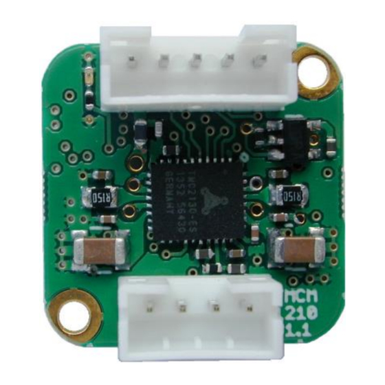
2 Features The TMCM-1210 is a highly compact 20mm x 20mm single axis stepper motor controller and driver board with RS485 interface. It has been designed in order to be mounted on the rear side of a NEMA8 (20mm flange size) stepper motor and offers an integrated hall-sensor based encoder IC in addition to a reference switch input for easy homing / search of reference position. -
Page 5: Order Codes
A cable loom set is available for this module, also: Order code Description TMCM-1210-CABLE Cable loom for TMCM-1210. Contains (see chapter 4.3, also): 1x cable loom for Power, RS485 and HOME connector 1x cable loom for Motor connector Table 3.2: Cable loom order code... -
Page 6: Mechanical And Electrical Interfacing
Figure 4.1 Dimensions of TMCM-1210 and position of mounting holes (with comparison of size) 4.2 Board mounting considerations The TMCM-1210 offers two metal plated mounting holes. Both mounting holes are connected to power supply ground. Please keep this in mind when mounting the board to the rear side of a motor. -
Page 7: Connectors
TMCM-1210 Hardware Manual (V0.93 / 2019-FEB-13) 4.3 Connectors The TMCM-1210 offers two connectors including the motor connector which is used for attaching the motor coils to the electronics. The Power, RS485 and HOME connector is used for power supply, RS485 serial wire communication and offers one digital input. -
Page 8: Power, Rs485 + Home Connector
Always keep the power supply voltage (VDD) below the upper limit of 30V! Otherwise the driver electronics will be seriously damaged. Especially, when the selected operating voltage is near the upper limit a regulated power supply is highly recommended. Copyright © 2015-2019 TRINAMIC Motion Control GmbH & Co. KG... -
Page 9: Motor Connector
For proper operation care has to be taken with regard to power supply concept and design. Due to space restrictions the TMCM-1210 includes just about 20µF/35V of supply filter capacitors. These are ceramic capacitors which have been selected for high reliability and long life time. - Page 10 TMCM-1210 Hardware Manual (V0.93 / 2019-FEB-13) RS485 For remote control and communication with a host system the TMCM-1210 provides a two wire RS485 bus interface. For proper operation the following items should be taken into account when setting up an RS485...
- Page 11 Figure 4.8: Bus lines with resistor (Bias) network at both ends Certain RS485 interface converters available for PCs already include these additional resistors (e.g. USB-2- 485 with bias network at one end of the bus). Copyright © 2015-2019 TRINAMIC Motion Control GmbH & Co. KG...
-
Page 12: Motor Driver Current
SAP 6, 0, <value> // set run current SAP 7, 0, <value> // set standby current (read-out value with GAP instead of SAP. Please see separate TMCM-1210 firmware manual for further information) Motor current Resulting motor current based on motor current setting... -
Page 13: On-Board Leds
Short programming pads on bottom of PCB as shown in figure 7.1. Switch ON power supply (on-board LED should start flashing fast). Switch OFF power supply. Remove short circuit. Figure 7.1 Reset to factory default values (bottom view of pcb) Copyright © 2015-2019 TRINAMIC Motion Control GmbH & Co. KG... -
Page 14: Emc Considerations
Tests have shown that it is possible to meet Class B emission standards using the bare TMCM-1210 (motor and power connected) with the motor running slowly at maximum current (0.7A RMS) and +24V supply voltage without additional / external filters. -
Page 15: Operational Ratings
Symbol Parameter Unit Number of nodes connected to single RS485 RS485 network Maximum bit rate supported on RS485 9600 1000000 bit/s RS485 connection Table 9.3: Operational ratings of RS485 interface Copyright © 2015-2019 TRINAMIC Motion Control GmbH & Co. KG... -
Page 16: Functional Description
TMCM-1210 Hardware Manual (V0.93 / 2019-FEB-13) 10 Functional Description The TMCM-1210 is a highly integrated controller/driver module which can be controlled via several serial interfaces. Communication traffic is kept low since all time critical operations (e.g. ramp calculations) are performed on board. -
Page 17: Revision History
Footprint of protection diode for external digital input corrected Table 11.2: Hardware revision 12 References [JST] JST connector http://www.jst.com [TMC2130] TMC2130 datasheet Manual available on http://www.trinamic.com [TMCL-IDE] TMCL-IDE User Manual Manual available on http://www.trinamic.com. Copyright © 2015-2019 TRINAMIC Motion Control GmbH & Co. KG...
Need help?
Do you have a question about the TMCM-1210 and is the answer not in the manual?
Questions and answers