Table of Contents
Advertisement
Quick Links
Advertisement
Table of Contents

Related Manuals for Keysight Technologies U9397A


Summary of Contents for Keysight Technologies U9397A
- Page 1 Keysight U9397A/C FET Solid State Switch (SPDT) Operating and Service Manual...
- Page 2 FAR 27.401 or DFAR could result in personal injury or death. 227.7103-5 (c), as applicable in any Do not proceed beyond a WARNING technical data. notice until the indicated conditions are fully understood and met. Keysight U9397A/C Operating and Service Manual...
-
Page 3: Environmental Conditions
2026-1 (modified) Storage condition: Altitude – <15300 meters (50000 feet) Direct discharge: – 4 kV (to outer conductor) per IEC 61000-4-2 ESD immunity Air discharge: – 8 kV (to center conductor) per IEC 61000-4-2 Keysight U9397A/C Operating and Service Manual... -
Page 4: Waste Electrical And Electronic Equipment (Weee) Directive 2002/96/ Ec
To contact Keysight for sales and technical support, refer to the support links on the following Keysight websites: – www.keysight.com/find/mta (product-specific information and support, software and documentation updates) – www.keysight.com/find/assist (worldwide contact information for repair and service) Keysight U9397A/C Operating and Service Manual... -
Page 5: Table Of Contents
......... . .25 Keysight U9397A/C Operating and Service Manual... - Page 6 THIS PAGE HAS BEEN INTENTIONALLY LEFT BLANK. Keysight U9397A/C Operating and Service Manual...
- Page 7 ....12 Figure 1-2 Block diagram on the operation of U9397A/C FET solid state switches ......14...
- Page 8 THIS PAGE HAS BEEN INTENTIONALLY LEFT BLANK. Keysight U9397A/C Operating and Service Manual...
- Page 9 ......15 Table 2-1 RF specifications for U9397A/C FET solid state switches Table 2-2 Absolute maximum rating for U9397A/C FET solid state switches .
- Page 10 THIS PAGE HAS BEEN INTENTIONALLY LEFT BLANK. Keysight U9397A/C Operating and Service Manual...
- Page 11 Keysight U9397A/C FET Solid State Switch (SPDT) Operating and Service Manual General Information Product Overview Circuit Logic This chapter provides an overview of the Keysight U9397A/C FET solid state switches.
-
Page 12: General Information
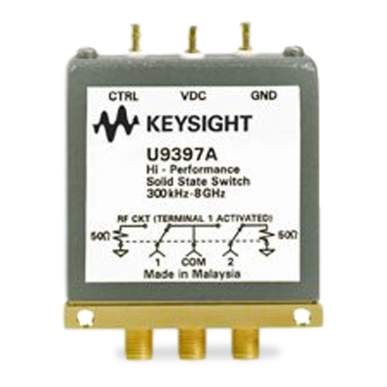
General Information Product Overview The Keysight U9397A/C is GaAs FET Monolithic Microwave Integrated Circuit (MMIC) based solid state switches which provide superior performance in isolation, settling time, video leakage, and insertion loss across a broad operating frequency range. Figure 1-1... -
Page 13: Features
– Minimize crosstalk with exceptionally high isolation 100 dB at 8 GHz. – Maintain fast throughput with industry leading settling time for FET switches of 500 μs – Integrated TTL/CMOS driver eliminated the need for external drivers Keysight U9397A/C Operating and Service Manual... -
Page 14: Circuit Logic
General Information Circuit Logic Keysight U9397A/C switches have a GaAs FET MMIC at each RF ports, and the integrated TTL/CMOS driver is configured in such a way that when either the RF1 or RF2 port is not selected to RFCOM, it will be terminated to 50 Ohm as shown in Figure 1-2. - Page 15 General Information Table 1-2 Switch operation logic CTRL logic RFCOM to RF1 RFCOM to RF2 Low loss Isolated Isolated Low loss Keysight U9397A/C Operating and Service Manual...
- Page 16 General Information THIS PAGE HAS BEEN INTENTIONALLY LEFT BLANK. Keysight U9397A/C Operating and Service Manual...
- Page 17 Keysight U9397A/C FET Solid State Switch (SPDT) Operating and Service Manual Specifications Specifications Physical Specifications This chapter provides the specifications of the U9397A/C FET solid state switches.
-
Page 18: Specifications
Typical characteristics are included for additional information only and they are not specifications. These are denoted as “typical”, “nominal”, or “approximate” and are printed in italics. Table 2-1 RF specifications for U9397A/C FET solid state switches Specification U9397A U9397C Frequency range... - Page 19 Current sourcing at RF1 or RF2 Vdc bias CTRL input high voltage +2.4 CTRL input low voltage +0.8 [a] Operation in excess of any one of these may result in permanent damage to the products. [b] Sinking not allowed. Keysight U9397A/C Operating and Service Manual...
-
Page 20: Physical Specifications
Specifications Physical Specifications Table 2-3 Figure 2-1 illustrate the physical specifications of U9397A/C FET solid state switches. Table 2-3 U9397A/C FET solid state switches physical specifications Dimensions Figure 2-1 Net weight, kg (lb) 0.055 (0.121) Dimensions are in milimeters (inches). -
Page 21: Keysight U9397A/C Fet Solid State Switch (Spdt)
Keysight U9397A/C FET Solid State Switch (SPDT) Operating and Service Manual Operating Guide Installation Operating Instructions Performance Tests Service Instructions This chapter describes the installation, operating instructions, and service information of the U9397A/C. -
Page 22: Operating Guide
“Sales and Technical Support” on page 4 of this manual for the Keysight Technologies nearest to you. Attach a tag indicating the type of service required, return address, model number, and serial number. Mark the container FRAGILE to insure careful handling. In any correspondence, refer to the instrument by model number and serial number. -
Page 23: Operating Instructions
(insertion loss) measurement is the best way to determine if the switch is faulty by applying the appropriate logic to the CTRL pin. Network analyzer Network analyzer Keysight Keysight U9397A/C U9397A/C Solid state switch Solid state switch Figure 3-1 Connection to perform quick check Keysight U9397A/C Operating and Service Manual... - Page 24 2-1. 4 If RF2 of the switch is connected to Port 2, apply logic ‘1’ to CTRL. This should yield low loss from RFCOM to RF2. S should not exceed specification in Table 2-1. Keysight U9397A/C Operating and Service Manual...
-
Page 25: Performance Tests
The U9397A/C FET solid state switches do not have internal adjustments and should not be opened. Repair The U9397A/C FET solid state switches are not recommended for repair as most components are not easily removed. Maintenance The connectors, particularly the connector faces, must be kept clean. For instruction on connecting and care of your connectors, refer to the Microwave Connector Care Quick Reference Card (08510-90360). - Page 26 Operating Guide THIS PAGE HAS BEEN INTENTIONALLY LEFT BLANK. Keysight U9397A/C Operating and Service Manual...
- Page 27 This information is subject to change without notice. Always refer to the Keysight website for the latest revision. © Keysight Technologies 2007-2017 Edition 4, August 30, 2017 Printed in Malaysia *U9397-90001* U9397-90001 www.keysight.com...
Need help?
Do you have a question about the U9397A and is the answer not in the manual?
Questions and answers