Table of Contents
Advertisement
Quick Links
Advertisement
Table of Contents

Related Manuals for Keysight Technologies U9400A


Summary of Contents for Keysight Technologies U9400A
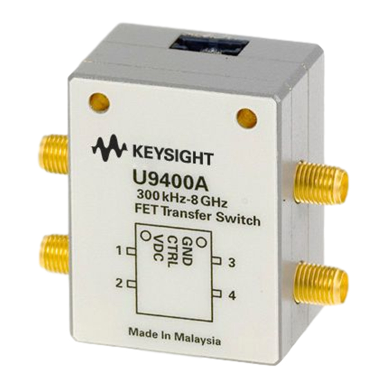
- Page 1 Keysight U9400A/C Solid State FET Transfer Switches Operating and Service Manual...
-
Page 2: Copyright Notice
FAR 27.401 or DFAR could result in personal injury or death. 227.7103-5 (c), as applicable in any Do not proceed beyond a WARNING technical data. notice until the indicated conditions are fully understood and met. Keysight U9400A/C Operating and Service Manual... -
Page 3: Environmental Conditions
– 50 to 2000 Hz, 7.0 G rms, 15 minutes, per MIL-STD-883F, Method 2026-1 (modified) Direct discharge – 1.0 kV per IEC 61000-4-2 ESD immunity Air discharge – 2.5 kV per IEC 61000-4-2 [a] To outer conductor [b] To center conductor Keysight U9400A/C Operating and Service Manual... -
Page 4: Waste Electrical And Electronic Equipment (Weee) Directive 2002/96/ Ec
To contact Keysight for sales and technical support, refer to the support links on the following Keysight websites: – www.keysight.com/find/mta (product-specific information and support, software and documentation updates) – www.keysight.com/find/assist (worldwide contact information for repair and service) Keysight U9400A/C Operating and Service Manual... -
Page 5: Table Of Contents
......... . .26 Keysight U9400A/C Operating and Service Manual... - Page 6 THIS PAGE HAS BEEN INTENTIONALLY LEFT BLANK. Keysight U9400A/C Operating and Service Manual...
-
Page 7: Keysight U9400A/C Operating And Service Manual
List of Figures Figure 1-1 U9400C and U9400A solid state FET transfer switches Figure 1-2 Diagram of U9400A/C switches in State A ..14 Figure 1-3 Diagram of U9400A/C switches in State B . - Page 8 THIS PAGE HAS BEEN INTENTIONALLY LEFT BLANK. Keysight U9400A/C Operating and Service Manual...
- Page 9 U9400A/C absolute maximum ratings ... .21 Table 3-3 U9400A/C physical specifications ....21 Keysight U9400A/C Operating and Service Manual...
- Page 10 THIS PAGE HAS BEEN INTENTIONALLY LEFT BLANK. Keysight U9400A/C Operating and Service Manual...
-
Page 11: Introduction
Keysight U9400A/C Solid State FET Transfer Switches Operating and Service Manual Introduction Product Overview Circuit Logic This chapter provides an overview of the Keysight U9400A/C Solid State FET Transfer Switches. -
Page 12: Product Overview
Introduction Product Overview The Keysight U9400A/C consists of 8/18 GHz solid state FET transfer switches which are developed based on GaAs FET Monolithic Microwave Integrated Circuit (MMIC). These solid state switches provide high isolation; low video leakage; superior insertion loss and return loss across a broad operating frequency range. -
Page 13: Features
– Prevent damage to sensitive devices or components with low video leakage of typically 90 mVpp – Maintain fast throughput with industry leading settling time for FET switches of 350 μs – Eliminate the need for external drivers with integrated TTL–compatible driver Keysight U9400A/C Operating and Service Manual... -
Page 14: Circuit Logic
Introduction Circuit Logic The Keysight U9400A/C switches come with an integrated TTL-compatible driver that is configured in such a way that when a TTL high (logic 1) is applied to the CTRL pin of the switch, the paths from Port 1 to Port 2 and Port 3 to Port 4 of the switch are at high isolation, while the paths from Port 1 to Port 3 and Port 2 to Port 4 are at low loss. - Page 15 Introduction RF Port 1 RF Port 2 TTL driver CTRL circuits RF Port 3 RF Port 4 Figure 1-3 Diagram of U9400A/C switches in State B Keysight U9400A/C Operating and Service Manual...
- Page 16 Introduction THIS PAGE HAS BEEN INTENTIONALLY LEFT BLANK. Keysight U9400A/C Operating and Service Manual...
-
Page 17: Installation
Keysight U9400A/C Solid State FET Transfer Switches Operating and Service Manual Installation Initial Inspection This chapter provides you important information on how to check and prepare your instrument for operation. -
Page 18: Initial Inspection
“Sales and Technical Support” on page 4 of this manual for the Keysight Technologies nearest to you. Attach a tag indicating the type of service required, return address, model number, and serial number. Mark the container FRAGILE to insure careful handling. In any correspondence, refer to the instrument by model number and serial number. -
Page 19: Specifications
Keysight U9400A/C Solid State FET Transfer Switches Operating and Service Manual Specifications Specifications This chapter provides the specifications of the U9400A/C solid state FET transfer switches. -
Page 20: Specifications
90 mVpp 90 mVpp Ω Ω Characteristic impedance (nominal) Connectors SMA (f) SMA (f) [a] Switching speed is based on 50% TTL to 90% RF (ON time) or 50% TTL to 10% RF (OFF time). Keysight U9400A/C Operating and Service Manual... -
Page 21: Physical Specifications
[a] Operation in excess of any one of these may result in permanent damage to the products. [b] Sinking is not allowed. Physical specifications Table 3-3 U9400A/C physical specifications Dimensions Net weight, kg (lb) Figure 3-1 0.095 (0.209) Keysight U9400A/C Operating and Service Manual... -
Page 22: Figure 3-1 Dimensions Of The U9400A/C Solid State Fet Transfer Switches
Specifications Dimensions in millimeters (inches) Figure 3-1 Dimensions of the U9400A/C solid state FET transfer switches Keysight U9400A/C Operating and Service Manual... -
Page 23: Operating Guide
Keysight U9400A/C Solid State FET Transfer Switches Operating and Service Manual Operating Guide Operating Instructions Performance Tests Service Instructions This chapter provides simple quick-check instructions to verify the U9400A/C’s functionality prior to usage. It also provides information on service and maintenance of the U9400A/C. -
Page 24: Operating Instructions
The S-parameter measurements are required to determine if the switch is working properly by applying the appropriate logic to the CTRL pin. Network analyzer Power supply TTL High/Low U9400A/C Figure 4-1 Quick-check configuration for U9400A/C Keysight U9400A/C Operating and Service Manual... - Page 25 5 Repeat steps 2 and 3 for Port 1 and Port 3 of the switch by applying logic ‘1’ (+2.4 V to +5.0 V) to CTRL. 6 Repeat steps 2 and 3 for Port 2 and Port 4 of the switch by applyingslogic ‘1’ (+2.4 V to +5.0 V) to CTRL. Keysight U9400A/C Operating and Service Manual...
-
Page 26: Performance Tests
Operating Guide Performance Tests The U9400A/C solid state FET transfer switches can be tested to the accuracy of the specifications with a network analyzer or equivalent equipment of suitable accuracy. If a network analyzer is available, test the instrument using the procedure in the analyzer's operating manual. - Page 27 This information is subject to change without notice. Always refer to the English version at the Keysight website for the latest revision. © Keysight Technologies 2008 - 2018 Edition 4, February 1, 2018 Printed in Malaysia *U9400-90001* U9400-90001 www.keysight.com...
Need help?
Do you have a question about the U9400A and is the answer not in the manual?
Questions and answers