fantastic furniture Bridge Manual
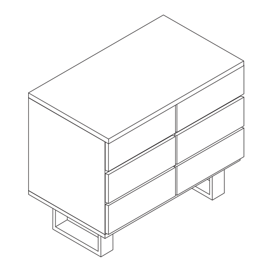
Dresser 6 drawer oak
Hide thumbs
Also See for Bridge:
- Assembly instructions manual (19 pages) ,
- Manual (14 pages) ,
- Manual (9 pages)
Advertisement
Quick Links
Advertisement

Subscribe to Our Youtube Channel
Related Manuals for fantastic furniture Bridge


Summary of Contents for fantastic furniture Bridge
- Page 1 Bridge Dresser 6 Drawer Oak...
-
Page 5: Parts List
Top Panel (P1) Back Panel 6 x Supports Panel (P7) Right Panel (P6) (P3) Back Panel (P7) Parts list Back Support Panel Drawer Bottoms Middle Panel (P8) Top Panel (P1) (P14) (P5) Bottom Panel (P2) Right Panel (P3) Drawer Supports (P15) Left Panel (P4) Middle Panel (P5) - Page 6 2 x Short Bolts 1 x Support Leg (H16) (P17) 1 x Allen Key (H7) Using 2 x short bolts (H16) secure the Suppot Leg(P17)to the bottom panel (P2), tightening completely with allen key (H7). 2 x Legs 12 x Washers (P16) (H5) 12 x Bolts...
- Page 7 6 x Dowels (H3) (P2) With assistance, carefully turn the bottom panel upright. Insert 6 x dowels (H3) into the bottom panel (P2). (H10) (H15-2) 6 x Left Runner 36 x Short Screws Track (H10) (H15-1) (H15-2) (H15-1) 6 x Right Runner (H15-1) Track (H15-2)
- Page 8 (H1) (H4) 3 x L ong Dowels 10 x Cam Bolts (H4) (H1) (H1) (P5) (H1) Phillips Head Screwdriver Insert 3 x long dowels (H4) and secure 5 x cam bolts (H1) to middle panel (P5), tightening with the a phillips head screwdriver. Repeat this process for the other side of the middle panel (P5).
- Page 9 Note: attach the back support panel (P8) on the side closest to the grooves. Phillips Head 10 x Cam Nuts Screwdriver (H2) Align and attach 3 x support panels (P6) and 1 x back support panel (P8) to the Left panel (P4).
- Page 10 With assistance, carefully turn the assembled frame upright. Slide 2 x back panels(P7) into the grooves of the left, right and middle panel (P3, P4, P5). (H7) (H17) 6 x Bolts 1 x Allen Key (H17) (H7) With assistance, align the bottom panel (P2) onto the assembled frame as shown. Ensure the grooves on all panels align.
- Page 11 With assistance, carefully turn the assembled frame upright. Slide 2 x back panels(P7) into the groove of right panel, left panel and middle panel (P3, P4, P5) as shown. (P1) 6 x Dowels 6 x Cam Bolts (H1) (H3) Phillips Head Screwdriver Insert 6 x dowels (H3) into the top panel (P1).
- Page 12 (H2) (H2) With assistance, carefully align and lower the top panel (P1) onto the assembled , unit as shown. Insert 6 x cam nuts (H2) into the right left and middle panels (P3, P4 P5), rotating the cam nuts so the arrows point towards the incoming cam bolts.
- Page 13 Align and attach 1 x drawer left panel (P12) and 1 x drawer right panel (P13) and 1xDrawer Support(P15) to 1 x drawer door (P9,P10). Ensure the grooves on the drawer panels (P12, P13) align as shown. Insert 4 x cam nuts (H2) into the panels (P12, P13), rotating the cam nuts so the arrow points towards incoming cam bolts.
- Page 14 (H10) (H15-4) (H10) (H2) (H10) (H10) (H10) 3 x Left 3 x Right Runner Runner (H15-3) (H15-4) (H15-3) 36 x Short Screws Phillips Head (H10) Screwdriver Note: Ensure the wheels on the runners are at the back of the drawer as shown. 12 x Cam Nuts (H2) Secure 1 x left runner (H15-3) and 1 x right runner (H15-4) to the assembled drawer...
- Page 15 12 x Short Screw (H10) (H9) Insert 12 x wedges (H9) into the back of the dresser as shown. Secure using 12 x short screws (H10), tightening with the phillips head screwdriver. We strongly recommend this product is permanently fixed to the wall or other suitable surface.
- Page 16 (H11) 2 x Washers (H11) With assistance, carefully move the dresser to its final position. Attach the wall straps (H12) to the wall, ensuring it is firmly attached and secure. If required, the levelling feet on the 2 x legs (P15) can be adjusted so the unit is level. Page 16...
Need help?
Do you have a question about the Bridge and is the answer not in the manual?
Questions and answers