Advertisement
Quick Links
Advertisement

Related Manuals for fantastic furniture Bridge Bedside 1 Drawer


Summary of Contents for fantastic furniture Bridge Bedside 1 Drawer
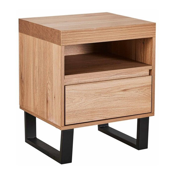
- Page 1 Bridge Bedside 1 Drawer Oak...
- Page 4 Top Panel (P1) Back Panel Right Panel (P5) (P3) Shelf (P6) Drawer Back (P9) Support Panel (P7) Left Panel (P4) Drawer Door (P8) Top Panel (P1) Drawer Bottom Bottom Panel (P2) (P12) Right Panel (P3) Left Panel (P4) Bottom Panel Back Panel (P5) (P2) Shelf (P6)
- Page 5 12 x Washers 12 x Bolts (H4) (H5) 4 x Levelling Feet 1 x Allen Key (H8) (H7) Attach the 2 x legs (P13) to the bottom panel (P2) using 12 x bolts (H5) and 12 x washers (H4), completely tightening using the allen key (H7). Screw in the 4 x levelling feet (H8) into the 2 x legs (P13) as shown.
- Page 6 4 x Cam Bolts 8 x Dowels (H1) (H3) Phillips Head Screwdriver Insert 4 x dowels (H3) into right panel (P3) and secure 2 x cam bolts (H1) to right panel (P3), tightening using a phillips head screwdriver. Repeat this step for the left panel (P4). 4 x Cam Nuts Phillips Head (H2)
- Page 7 4 x Cam Nuts Phillips Head (H2) Screwdriver Align and attach the assembled frame onto the bottom panel (H2) as shown, ensuring the grooves on the right panel (P3), left panel (P4) and bottom panel (P2) align. Insert 4 x cam nuts (H2) into the top of the right panel (P3) and left panel (P4), rotating the cam nuts so the arrow points towards the incoming cam bolt.
- Page 8 4 x Cam Nuts Phillips Head (H2) Screwdriver Align and attach the top panel (P1) onto the assembled frame as shown. Insert 4 x cam nuts (H2) into the top of the right panel (P3) and left panel (P4), rotating the cam nuts so the arrow points towards the incoming cam bolts.
- Page 9 Attach drawer left panel (P10) and drawer right panel (P11) to drawer door (P8), ensuring the grooves on all the panels align as shown. Slide the drawer bottom (P12) through the grooves on all drawer panels (P10, P11, P8) as shown. Insert 4 x cam nuts (H2) into the drawer left panel (P10) and drawer right panel (P11), rotating the cam nut (H2) so the arrow points towards the incomcing cam bolt.
- Page 10 (H6) (H6) (H9-4) (H6) Left Right (H6) Runner Runner (H9-3) (H9-4) (H9-3) 4 x Screws Phillips Head (H6) Screwdriver Secure the left runner (H9-3) and right runner (H9-4) to the assembled drawer using 4 x short screws, tightening using a phillips head screwdriver. Ensure the wheels on the runners are towards the back of the drawer as shown.
- Page 11 Slide the assembled drawer into bedside H 14 4 x Screws (H14) (H6) Insert 4 x wedges (H14) into the back of the unit as shown. Secure using 4 x screws (H6), tightening with the phillips head screwdriver. Page 11...
- Page 12 We strongly recommend this product is permanently fixed to the wall or other suitable surface. 1 x Medium Screw (H13) (H11) 1 x Wall Strap (H12) Attach wall strap (H12) to the top panel (P1) using washer (H11) and medium screw (H13). Tighten using the phillips head screwdriver. (H11) 1 x Washer (H11)
- Page 13 Page 13...
Need help?
Do you have a question about the Bridge Bedside 1 Drawer and is the answer not in the manual?
Questions and answers