fantastic furniture Bridge Assembly Instructions Manual
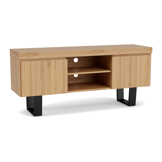
Ent unit large 2 drawer
Hide thumbs
Also See for Bridge:
- Manual (16 pages) ,
- Assembly instructions manual (7 pages) ,
- Manual (9 pages)
Advertisement
Quick Links
Advertisement

Related Manuals for fantastic furniture Bridge


Summary of Contents for fantastic furniture Bridge
- Page 1 Bridge Ent Unit Large 2 Drawer...
- Page 2 Recommended weight capacity: 80kgs...
-
Page 5: Hardware Pack
Top Panel (P1) Right Panel Back Panel (P3) (P9) Middle Back Panel (P10) Middle Right Panel (P5) (P17) (P15) Shelf (P18) Top Panel (P1) (P8) Back Panel Middle Left Panel Bottom Panel (P2) Drawer Front (P9) (P6) (P13) (P16) Right Panel (P3) Right Door Shelf (P11) - Page 6 Note: We strongly recommend assembling this entertainment unit on a soft surface to minimise the risk of damaging the unit. 4 x Short Bolts 2 x Support Legs (H14) (H13) 1 x Allen Key (H9) Using 4x Short Bolts (H14), secure 2x Support Legs (H13) to the Bottom Panel (P2) by tightening with the Allen Key (H9). 12 x Washers 12 x Bolts (H7)
-
Page 7: Two People
TWO PEOPLE REQUIRED 8 x Dowels 8 x Cam Bolts (H1) (H3) (P2) Phillips Head Screwdriver With assistance, carefully turn the Bottom Panel upright. Insert 8x Dowels (H3) into the Bottom Panel (P2). Secure 8x Cam Bolts (H1) to the Bottom Panel (P2), tightening with the Phillips Heads Screwdriver. (H3) (P3) (P4) - Page 8 (H4) (H4) (P6) (P6) (H1) (H1) 6 x Cam Bolts 2 x Dowels (H3) (H1) (H3) (H4) 6 x Long Dowels Phillips Head (H4) (P5) Screwdriver (H1) Insert 2 x Long Dowels(H4) into Middle Right Panel(P5) as shown, Insert 2 x Dowels(H3) into Middle Right Panel(P5) and secure 2 x Cam Bolts(H1) to Middle Right Panel(P5) as shown. Insert 4 x Long Dowels(H4) into Middle Left Panel(P6) and secure 2 x Cam Bolts(H1) to Middle Left Panel(P6) by tightening with the Phillips Head Screwdriver,turn over,then secure 2 x Cam Bolts(H1) to other side of Middle Left Panel(P6) by tightening with the Phillips Head Screwdriver as shown.
- Page 9 Ensure the grooves on the Middle Right TWO PEOPLE Panel (P5) are located at the back of the unit. (H2) REQUIRED (P5) 4 x Cam Nuts Phillips Head (H2) Screwdriver (P8) (P6) (P7) Attach 1 x Shelf(P8) and 1 x Support(P7) to Middle Right Panel(P5) and Middle Left Panel(P6) as shown. Insert 4 x Cam Nuts(H2) into Shelf(P8) as shown.
- Page 10 TWO PEOPLE REQUIRED (P5) (P6) (P4) With assistance, carefully turn the partially assembled unit upright. TWO PEOPLE (P3) REQUIRED (P7) (P5) 2 x Cam Nuts Phillips Head (H2) Screwdriver (P6) (H2) (P4) Attach 1x Support Rail (P7) to the Right Panel (P3) and Middle Right Panel (P5). Insert 2x Cam Nuts (H2) into the Right Panel (P3) as shown.
- Page 11 (P9) (P3) (P10) (P5) (P9) (P6) (P4) Slide Back Panels (P9) and Middle Back Panel (P10) into the grooves of the Left Panel (P4), Middle Left Panel (P6), Middle Right Panel (P5) and Right Panel (P3) as shown. (H3) (H1) 8 x Cam Bolts 8 x Dowels (H3)
- Page 12 TWO PEOPLE REQUIRED (P1) 8 x Cam Nuts Phillips Head (H2) (P3) (H2) Screwdriver (P5) (P6) (P4) Insert 8x Cam Nuts (H2) into the Left Panel (P4), Middle Left Panel (P6), Middle Right Panel (P5) and Right Panel (P3) as shown. Rotate the Cam Nuts (H2) so the arrows point towards the incoming Cam Bolts.
- Page 13 16 x Short Screws Phillips Head (H6) Screwdriver (P5) (P11) (P4) (P12) (H5) (H6) With assistance, carefully align the 2x Hinges on the Right Door (P11) to the Middle Right Panel (P5) and secure with 8x Short Screws (H6) by tightening with the Phillips Head Screwdriver. Repeat this step for the Left Door (P12). (P3) 2 x Left Runner 2 x Right Runner...
- Page 14 12 x Cam Bolts Phillips Head (H1) Screwdriver Attach 6x Cam Bolts (H1) to the first Drawer Front (P13) as shown by tightening with the Phillips Head Screwdriver. Repeat this step for the second Drawer Front (P14). 8 x Cam Nuts Phillips Head (H2) Screwdriver...
- Page 15 (P13) (H16) (P15) (H16) (H16) 12 x Long Screws (H16) Phillips Head (H16) Screwdriver (H16) (P14) (H16) (P15) (H16) (H16) (H16) (H16) Align 1x Drawer Back (P15) to the first assembled drawer, ensuring the pre-drilled holes on the Left Drawer Side (P16), Right Draw Side (P17) and Drawer Support (P19) align with the pre-drilled holes on the Drawer Back (P15).
- Page 16 Slide the 2x assembled drawers into the assembled unit 12 x Short Screws (H6) Insert 12x Wedges (H11) into the corners of each back panel (P9 & P10) as shown. Secure using 12x Short Screws (H6) and tighten with the Phillips Head Screwdriver. Page 16...
- Page 17 2 x Medium Screws (H14) (H17) 2 x Wall Straps (H18) from Toppling. We strongly recommend that this product is permanently fixed to the wall or another suitable surface. Use 1x Washer (H17) and 1x Medium Screw (H14) to connect 1x Wall Strap (H18) to the Top Panel (P1) as shown, tightening with the Phillips Head Screwdriver.
- Page 18 STEP 25.1 STEP 25.2 STEP 25.3 STEP 25.4 Page 18...
- Page 19 Page 19...
Need help?
Do you have a question about the Bridge and is the answer not in the manual?
Questions and answers