Table of Contents
Advertisement
Quick Links
Advertisement
Table of Contents

Related Manuals for Advantech WISE-2410X-A02


Summary of Contents for Advantech WISE-2410X-A02
- Page 1 User Manual WISE-2410X-A02 Explosion Proof LoRaWAN Smart Vibration Sensor...
- Page 2 The documentation and the software included with this product are copyrighted 2020 by Advantech Co., Ltd. All rights are reserved. Advantech Co., Ltd. also reserves the right to improve the products described in this manual at any time without notice. No part of this manual may be reproduced, copied, translated, or transmitted in any form or by any means without the prior written permission of Advantech Co., Ltd.
- Page 3 Declaration of Conformity Notice to OEM integrator 1. In the users manual of the end of product, the end user has to be informed to keep at least 20cm separation with the antenna while this end product is installed and operated.
- Page 4 Technical Support and Assistance Visit the Advantech website at www.advantech.com/support to obtain the latest product information. Contact your distributor, sales representative, or Advantech's customer service center for technical support if you need additional assistance. Please have the following information ready before calling: –...
- Page 5 Packing List Before setting up the system, check that the items listed below are included and in good condition. If any item does not accord with the table, please contact your dealer immediately. WISE-2410X ◼ 1 x WISE-2410X module ◼ 1 x Mounting stud (1/4-28 UNF x 9.4Lmm) ◼...
- Page 6 NCC 警语 第十二條 經型式認證合格之低功率射頻電機,非經許可,公司、商號或使用者均不得 擅自變更頻率、加大功率或變更原設計之特性及功能。 第十四條 低功率射頻電機之使用不得影響飛航安全及干擾合法通信;經發現有干擾 現象時,應立即停用,並改善至無干擾時方得繼續使用。前項合法通信,指依電信法 規定作業之無線電通信。低功率射頻電機須忍受合法通信或工業、科學及醫療用電波 輻射性電機設備之干擾。 VCCI この装置は、クラス B 機器です。この装置は、住宅環境で使用することを目的とし ていますが、この装置がラジオやテレビジョン受信機に近接して使用されると、受 信障害を引き起こすことがあります。 使用説明書に従って正しい取り扱いをして下さい。 VCCI-B Ex marking string IECEx Certificate No.: IECEx UL 21.0053X ATEX Certificate No.: UL 21 ATEX 2614X Standard Information: IEC 60079-0 Edition 7 ◼...
-
Page 7: Table Of Contents
Contents Chapter Product Overview ........1 Series Family and Specifications..............2 Features.....................2 System Architecture..................2 Figure 1.1 System Architecture ...........2 Mechanical Design and Dimensions............3 Figure 1.2 WISE-2410 Dimension..........3 LED......................3 Figure 1.3 LED................3 Chapter Product Specification......5 Wireless Interface ..................6 General .....................6 Power......................6 Software....................7 Configuration Interface................7 Sensor Specifications................7 Chapter Mechanical and Hardware Installation... - Page 8 WISE-2410X Configuration..............28 4.2.1 Information Page ................ 28 4.2.2 Configuration ................29 4.2.3 IO Status..................31 4.2.4 Data Logger................33 4.2.5 Diagnostician................35 4.2.6 Downlink Command..............35 viii...
-
Page 9: Chapter 1 Product Overview
Chapter Product Overview... -
Page 10: Series Family And Specifications
Series Family and Specifications Function Model Description Explosion Proof Built-in 3 axis vibration and temperature sensor; WISE-2410X LoRaWAN Smart Built-in antenna, support LoRaWAN Vibration Sensor Features WISE-2410X ◼ Built-in 3 axis vibration and temperature sensor ◼ Provide 3 axis vibration features (Velocity RMS, acceleration peak, etc.) ◼... -
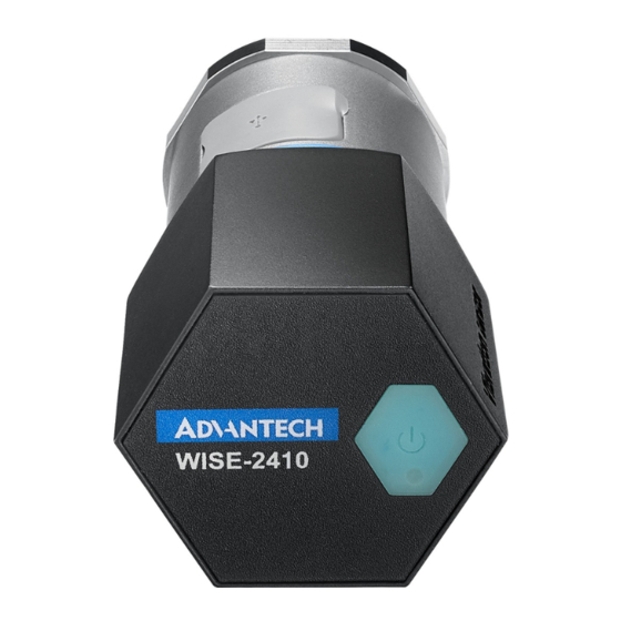
Page 11: Mechanical Design And Dimensions
Mechanical Design and Dimensions Figure 1.2 WISE-2410X Dimension Figure 1.3 LED Color Indication Behavior Turn on 2 sec when power on Status Green Turn on 1 ms when RF transmission Idle WISE-2410X User Manual... - Page 12 WISE-2410X User Manual...
-
Page 13: Chapter 2 Product Specification
Chapter Product Specification... -
Page 14: Wireless Interface
Wireless Interface Operating Frequency: US 902-928 (MHz) EU 863-870 (MHz) JP 920-928 (MHz) TW 920-925 (MHz) (AS923) Data Rate: 50 kbps at FSK mode EU 21.9 kbps at SF7 mode US 5.47 kbps at SF7 mode JP 5.47 kbps at CCS mode TW Antenna Gain: 902~928 MHz: 1 dBi 863~870 MHz: 1 dBi... -
Page 15: Software
Software ◼ Utility: WISE Studio Configuration Interface WISE-2410X ◼ Interface: COM port through Micro-B USB interface ◼ Connector: Micro-B USB ◼ USB chipset: Silicon Labs CP210x ◼ Driver: CP210x USB to UART Bridge VCP Drivers (https://support.advant- ech.com/support/DownloadSRDetail_New.aspx?SR_ID=1-13U9QTV&Doc_- Source=Download) Sensor Specifications Vibration Sensor ◼... - Page 16 WISE-2410X User Manual...
-
Page 17: Chapter 3 Mechanical And Hardware Installation
Chapter Mechanical and Hardware Installation... -
Page 18: Interface Introduction
Interface Introduction Figure 3.1 WISE-2410X Interface Introduction Note! Please DO NOT change/remove batteries or open the Micro-B USB port in HAZARDOUS LOCATIONS. Tighten two chassis Turn clockwise the top chassis to locking point to tighten bottom chassis. Figure 3.2 Tighten two chassis WISE-2410X User Manual... -
Page 19: Mounting
Mounting Applicable installation methods are briefly described in the following sections. 3.3.1 Installation Direction WISE-2410X Builds-in 3-axis vibration sensor. Please follow the following installation guide to make sure the eigenvalues from your device are correct. Figure 3.3 WISE-2410X Installation Direction on motor Figure 3.4 WISE-2410X Detail Installation Direction on motor WISE-2410X User Manual... -
Page 20: Stud Mount
3.3.2 Stud mount Dig a hole in motor surface (1/4-28). Fasten WISE-2410X and stud (1/4-28 to 1/4-28). Figure 3.5 Stud mount Fasten WISE-2410X (with stud) and hold of motor surface. Note! Please Wrench need to hold base steel (not contact chassis) when you use Wrench to fasten WISE-2410X(with stud) to hold of motor. -
Page 21: Adhesive Mounting Pad
3.3.4 Adhesive Mounting Pad Fasten WISE-2410X and stud, use adhesive epoxy glue(24hours) to stick on the motor surface. Figure 3.8 Adhesive Mounting Pad WISE-2410X User Manual... -
Page 22: Battery Replacement
Battery Replacement Only qualified person can do the battery replacement process. Slowly remove top chassis. Figure 3.9 Battery Replacement Step 1 Grab the Mylar and disconnect the connection between battery holder and PCBA. Figure 3.10 Battery Replacement Step 2 WISE-2410X User Manual... - Page 23 Figure 3.11 Battery Replacement Step 3 Plug in the battery pack and make sure the cable is hidden between the PCBA and the battery pack as follow. Please be award that WISE-2410X-A02 only allows 2 batteries. Figure 3.12 Battery Replacement Step 4...
- Page 24 Make the connection between battery holder and PCBA. Please make sure the cable has cross by the dent which is on the right side PCBA. Figure 3.13 Battery Replacement Step 5 Figure 3.14 Battery Replacement Step 6 WISE-2410X User Manual...
-
Page 25: Chapter 4 System Configuration
Chapter System Configuration... -
Page 26: Sensor And Gateway Connections
Sensor and Gateway Connections 4.1.1 Sensor (WISE-2410X) configuration Download and install WISE Studio through https://support.advantech.com/support/new_default.aspx. Connect the module to your computer via the micro-USB port. Execute WISE Studio. Clicking Go to Configuration while it shows “available USB-Serial” in USB- Serial box, press Go To Configuration. - Page 27 Use web configuration in WISE Utility or press Open In Browser to open the web configuration in any browser (Google Chrome is recommended). Note: Web in WISE Utility is using IE browser. PC Browser Chrome Firefox IE11 IE10 Configuration File Upload Data Log Chart Data Log Export Click Information to check the basic information of the module.
-
Page 28: Lorawan Gateway (Wise-6610) Configuration
Click IO Status to check vibration and temperature data. 4.1.2 LoRaWAN gateway (WISE-6610) configuration Default IP of WISE-6610 is 192.168.1.1. Login- Username: root Password: root You can see the main page of Router; you can change IP in LAN if needed. WISE-2410X User Manual... - Page 29 LoRaWAN setting. Step1: Choose User Modules and LoRaWAN Gateway. You can see WISE-6610N100-A (Support NA frequency band), make sure all of these parameters are matching with the RF module setting on WISE-2410X. WISE-2410X User Manual...
- Page 30 If you want to know any items' description, you can refer WISE-6610 user manual. A new tab will pop-up after click on Network Server (http). Account: root Password: root WISE-2410X User Manual...
-
Page 31: Binding Process Between Wise-2410X And Wise-6610
4.1.3 Binding Process Between WISE-2410X and WISE-6610 This section will guide you to setup the connection between WISE-2410X and WISE- 6610. Enter the “Network Server (http)” in WISE-6610 gateway as follow. Create an end node device according the OTAA or ABP method. The following flow will use ABP mode for description the binding process. - Page 32 Click “Device” > “Activated (Nodes)” > “+ Create”. A. DevAddr: the device address of an end node. Copy-pate “Device Address” from WISE-2410X “RF module” tab. B. Profile: select the model name of the WISE-6610 which used for Network Server role. In this demo, a US version is used to connect with WISE-2410X NA version.
- Page 33 Back to WISE-2410X configuration setting page. Click “Configuration” > “RF Mod- ule” and choose “LoRaWAN” for RF operation mode setting on WISE-2410X. Create a “network server” gateway. Copy-paste the MAC address from “LoRaWAN radio” > “LoRaWAN Gateway Identifier”. Then click on “submit”. WISE-2410X User Manual...
- Page 34 WISE-2410X User Manual...
- Page 35 Connection Verify. A. Click “Application Server” > “Status”. Here shows the end nodes if packets are received by gateway from an end node. B. Click “Detail”. The gateway will help to pre-parsing the data payload if the “App Arguments” input correctly. C.
-
Page 36: Wise-2410X Configuration
WISE-2410X Configuration All functions of WISE Studio for WISE-2410X is below: System Function Item Functional Description Display module name, Network status, Power status, Information Firmware version. ◼ Module Information ◼ RF related setting ◼ Date/time, time zone settings ◼ Schedule of when sensor should start measure- Configuration ment ◼... -
Page 37: Configuration
◼ Firmware – Firmware Upload: To update the firmware, click “Firmware Upload” to update file. The latest official firmware releases are available on the Advantech sup- port website (http://support.advantech.com/). – Configuration File Upload: User can upload their specific “Configuration File”. - Page 38 ◼ Scheduling: Data reports interval setting with optional weekly scheduling setting Based on application scenario, user can set scheduling of WISE-2410X. – Mode: Basic/Advance – Day: Mask for Sunday ~ Saturday – Start time: 00: 00 ~ 23: 59 – End time: 00: 00 ~ 23: 59 –...
-
Page 39: Io Status
4.2.3 IO Status Click IO Status to check vibration and temperature data. User can easily to see the detail data of all channels. User can choose channel 0, 1, 2 which means x, y, z axis to see the detailed vibration features (Velocity RMS, Acceleration Peak, and total eight features). - Page 40 ◼ Temperature alarm – Please select Channel 3 for Temperature sensor configuration. – Sensor Offset Value: Offset setting between measurement temperature value and real temperature value. – Enable: WISE-2410X will upload an alarm message according to the user- defined threshold value. If WISE-2410X detected a higher temperature value than the threshold setting, WISE-2410X will send a temperature alarm mes- sage to a gateway.
-
Page 41: Data Logger
4.2.4 Data Logger Configure or query logs stored in module. Data Configuration ◼ Log Conditions Default setting is to record the Velocity RMS alarm message if user has set a threshold on Velocity RMS values. – By Period: Enable means the log function will run by period which includes the Velocity RMS alarm message. - Page 42 Local Data Query ◼ Push Data Query Format – UUID: Enable or Disable the UUID. – MAC ID: Enable or Disable the MAC ID. – Timestamp: Local date and time (GMT) or Coordinated universal time (UTC). ◼ Query Filter – Filter Mode: User can choose No Filter Enable, Time Filter or Amount of Lat- est Data.
-
Page 43: Diagnostician
4.2.5 Diagnostician Display any errors detected by module. 4.2.6 Downlink Command For better user experience, WISE-2410X supports to config time and update interval remotely. Please contact local FAE for more detail technical supports. WISE-2410 User Manual... - Page 44 No part of this publication may be reproduced in any form or by any means, such as electronically, by photocopying, recording, or otherwise, without prior written permission of the publisher. All brand and product names are trademarks or registered trademarks of their respective companies. © Advantech Co., Ltd. 2020...
Need help?
Do you have a question about the WISE-2410X-A02 and is the answer not in the manual?
Questions and answers