Table of Contents
Advertisement
Quick Links
Advertisement
Table of Contents

Related Manuals for Advantech WISE-S100


Summary of Contents for Advantech WISE-S100
- Page 1 User Manual WISE-S100...
- Page 2 No part of this manual may be reproduced, copied, translated or transmitted in any form or by any means without the prior written permission of Advantech Co., Ltd. Information provided in this manual is intended to be accurate and reliable. How- ever, Advantech Co., Ltd.
- Page 3 (2) this device must accept any interference received, including interference that may cause undesired operation. Technical Support and Assistance Visit the Advantech web site at www.advantech.com/support where you can find the latest information about the product. Contact your distributor, sales representative, or Advantech's customer service center for technical support if you need additional assistance.
- Page 4 1 x China RoHS Declaration Note! The 2m cable is installed on WISE-S100 in default package. Safety Precaution - Static Electricity Follow these simple precautions to protect yourself from harm and the products from damage. Disconnect power before making any configuration changes. The sudden rush of power as you connect a jumper or install a card may damage sensitive electronic components.
- Page 5 The sound pressure level at the operator's position according to IEC 704-1:1982 is no more than 70 dB (A). DISCLAIMER: This set of instructions is given according to IEC 704-1. Advantech disclaims all responsibility for the accuracy of any statements contained herein.
- Page 6 WISE-S100 Series User Manual...
-
Page 7: Table Of Contents
Ambient Light Sensor................8 Mechanical ....................8 Environmental ................... 8 Cable Wiring and Ping Assignment............9 Table 3.1: WISE-S100 Cable Definition ........9 Figure 3.1 WISE-S100 Connector Pin Assignment ..... 9 Chapter Firmware Specification .....11 Operation Mode ..................12 Configuration................... 14 Light Sensor Channel Configuration ............ - Page 8 WISE-S100 Series User Manual viii...
-
Page 9: Chapter 1 Product Introduction
Chapter Product Introduction... -
Page 10: General Introduction
No Need to Stop the Machinery While Installation WISE-S100 is able to detect the light status by light colors, such as light on, light off, slow blink, and fast blink. It has 8 built-in light sensors for quick installation to fulfill most tower light applications in the market. -
Page 11: Industrial Design
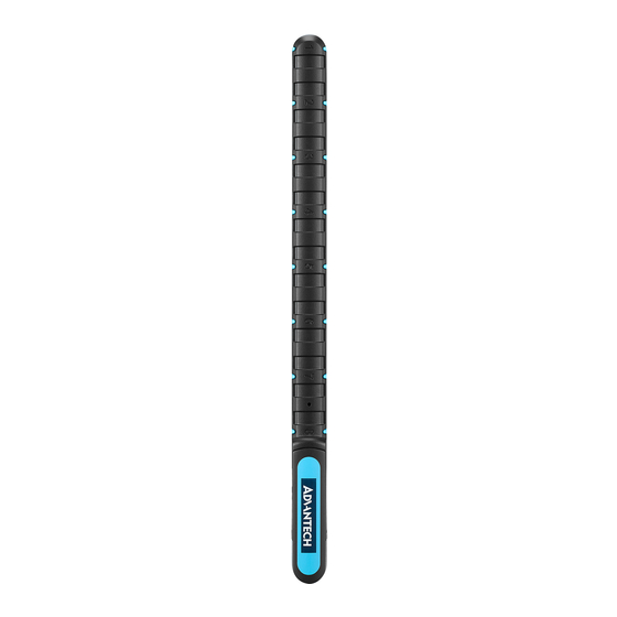
Industrial Design Figure 1.1 WISE-S100 Industrial Design Dimension Figure 1.2 WISE-S100 Dimension LED Indication Color Indication Behavior Steady On Modbus/RTU Mode Status Green On for 5 secs Serial Bus Mode (power saving) Blinking(2Hz) Sensor Initial Error WISE-S100 Series User Manual... -
Page 12: Packing List
1 x WISE-S100 Stack Light Monitoring Sensor 3 x Plastic Tie 1 x 2m Cable 1 x WISE-S100 Startup Manual 1 x China RoHS Declaration Note! The 2m cable is installed on WISE-S100 in default package. WISE-S100 Series User Manual... -
Page 13: Chapter 2 Hardware Installation
Chapter Hardware Installation... -
Page 14: Hardware Installation
Hardware Installation There are 8 light sensors inside WISE-S100 tower light. The idea of the design is for quick and easy installation without needing to stop the machine. All users need to do is to simply position a sensor indicator at the stack light and adjust WISE-S100 directly to match each light and mount them together. -
Page 15: Chapter 3 Hardware Specification
Chapter Hardware Specification... -
Page 16: Power
Temperature Drift: 0.02%/°C Mechanical Dimension (L x W x H): 220 x 14 x 12.8 (mm) Material: Polycarbonate (PC) Environmental Operating Temperature: -25~70 °C Storage Temperature: -40~80 °C Operating Humidity: 5~95% RH Storage Humidity: 0~95% RH WISE-S100 Series User Manual... -
Page 17: Cable Wiring And Ping Assignment
Cable Wiring and Ping Assignment The cable of the WISE-S100 stack light sensor is connected and installed in default package. The power input of the sensor is 3.3~30VDC. Please refer to the pin assignment via below table. Table 3.1: WISE-S100 Cable Definition... - Page 18 WISE-S100 Series User Manual...
-
Page 19: Chapter 4 Firmware Specification
Chapter Firmware Specification... -
Page 20: Operation Mode
2.Operation Mode Change The way to access WISE-S100 in Serial Bus Mode through WISE Studio when switching into Modbus Mode: - PC < --- > ADAM-4561 or any other USB to RS-485 converter < --- > WISE-S100 Step 3.Check the LED Indicator The LED indicator will be on when WISE-S100 is powered on. - Page 21 Step 5.Modbus Mode Enter into Configuration page through WISE Studio. Please take note of your RS-485 setting in case you could not search it. Note! Please refer to the Modbus Address table for more information. WISE-S100 Series User Manual...
-
Page 22: Configuration
Keep last value There are two functions for keep the last value of light on, off, slow blinking and fast blinking, please tick the function. – Keep Counter Value When Poweroff – Keep Total Time Value When Poweroff WISE-S100 Series User Manual... -
Page 23: Light Sensor Channel Configuration
Because of the resolution of the sensor is not always less than 1 as fol- lowing table, the user setting and actual light sensor setting might be inconsistent. For example, if a user sets 83850 on high limit, FW set 83845.12 on sensor but still show 83850 to user. WISE-S100 Series User Manual... -
Page 24: Light Sensor Data
Stop Bits The number of stop bits used Modbus/RTU general Configuration (only configurable in serial protocol mode) Parameter Description Values Default Modbus ID The modbus ID used 1~255 Modbus/RTU Address (not modifiable) See Appendix I WISE-S100 Series User Manual... -
Page 25: Serial Bus Interface
The interface of the serial bus is UART and two GPIOs to control the com- munication in power saving mode. The serial protocol defines the commands for exchanging module information, I/O configuration and value and upgrading the firm- ware of I/O module. WISE-S100 Series User Manual... - Page 26 WISE-S100 Series User Manual...
-
Page 27: Chapter A Modbus Table
Appendix Modbus Table... -
Page 28: Modbus Table
… Slow Blink state count Read 40079~ 00048 Write Read 40080 40081~ 00049 Write Read 40082 Clear slow blink state … … Write … … Fast Blink state count Read count 40095~ 00056 Write Read 40096 WISE-S100 Series User Manual... - Page 29 40221 Channel enable Write 40231~ Read/ 40232 Write Read/ … … Set Low limit (Lux) Write 40245~ Read/ 40246 Write 40247~ Read/ 40248 Write Read/ … … Set High Limit (Lux) Write 40261~ Read/ 40262 Write WISE-S100 Series User Manual...
- Page 30 41111~ 01064 Write Read 41112 41113~ 01065 Write Read 41114 Clear low state total High state total time (only … time (only enabled Write … Read enabled channel) (100 ms) channel) 41127~ 01072 Write Read 41128 WISE-S100 Series User Manual...
- Page 31 Note: For those "only enabled channel" items, it helps the Modbus address configu- ration contiguously. For example, if only channel 1 and channel 3 are enabled, the address of sensor value can be 41001~41002 for channel 1, 41003~41004 for channel3, and 41005 for channel 1 sensor status. WISE-S100 Series User Manual...
- Page 32 No part of this publication may be reproduced in any form or by any means, electronic, photocopying, recording or otherwise, without prior written permis- sion of the publisher. All brand and product names are trademarks or registered trademarks of their respective companies. © Advantech Co., Ltd. 2020...
Need help?
Do you have a question about the WISE-S100 and is the answer not in the manual?
Questions and answers