Advantech WISE-2410 User Manual
Lorawan smart condition monitoring sensor
Hide thumbs
Also See for WISE-2410:
- User manual (56 pages) ,
- Quick start manual (9 pages) ,
- Startup manual (2 pages)
Table of Contents
Advertisement
Advertisement
Table of Contents

Related Manuals for Advantech WISE-2410


Summary of Contents for Advantech WISE-2410
- Page 1 User Manual WISE-2410 LoRaWAN Smart Condition Monitoring Sensor...
- Page 2 The documentation and the software included with this product are copyrighted 2020 by Advantech Co., Ltd. All rights are reserved. Advantech Co., Ltd. also reserves the right to improve the products described in this manual at any time without notice. No part of this manual may be reproduced, copied, translated, or transmitted in any form or by any means without the prior written permission of Advantech Co., Ltd.
- Page 3 Radiation Exposure Statement: This equipment complies with FCC radiation exposure limits set forth for an uncon- trolled environment. This equipment should be installed and operated with minimum distance 20cm between the radiator & your body. WISE-2410 User Manual...
- Page 4 Technical Support and Assistance Visit the Advantech website at www.advantech.com/support to obtain the latest product information. Contact your distributor, sales representative, or Advantech's customer service center for technical support if you need additional assistance. Please have the following information ready before calling: –...
- Page 5 Before setting up the system, check that the items listed below are included and in good condition. If any item does not accord with the table, please contact your dealer immediately. WISE-2410 1 x WISE-2410 module 1 x Mounting stud (1/4-28 UNF x 9.4Lmm) ...
- Page 6 sudden rush of power after connecting a jumper or installing a card may dam- age sensitive electronic components. NCC 警语 第十二條 經型式認證合格之低功率射頻電機,非經許可,公司、商號或使用者均不得 擅自變更頻率、加大功率或變更原設計之特性及功能。 第十四條 低功率射頻電機之使用不得影響飛航安全及干擾合法通信;經發現有干擾 現象時,應立即停用,並改善至無干擾時方得繼續使用。前項合法通信,指依電信法 規定作業之無線電通信。低功率射頻電機須忍受合法通信或工業、科學及醫療用電波 輻射性電機設備之干擾。 VCCI この装置は、クラス B 機器です。この装置は、住宅環境で使用することを目的とし ていますが、この装置がラジオやテレビジョン受信機に近接して使用されると、受 信障害を引き起こすことがあります。 使用説明書に従って正しい取り扱いをして下さい。 VCCI-B WISE-2410 User Manual...
-
Page 7: Table Of Contents
Mounting ....................11 3.3.1 Installation Direction..............11 Figure 3.3 WISE-2410 Installation Direction on motor....11 Figure 3.4 WISE-2410 Detail Installation Direction on motor ..11 3.3.2 Stud mount.................. 12 Figure 3.5 Stud mount ............... 12 Figure 3.6 Stud mount ............... 12 3.3.3... - Page 8 IO Status..................31 4.2.4 Data Logger ................33 4.2.5 Diagnostician ................35 4.2.6 Downlink Command..............35 Get Raw Data from WISE-2410 .............. 36 4.3.1 Standard operation mode ............36 4.3.2 Real-Time operation mode ............38 Appendix A Modbus Address....... 39...
-
Page 9: Chapter 1 Product Overview
Chapter Product Overview... -
Page 10: Series Family And Specifications
IP66 enclosure System Architecture WISE-2410 transmits sensor data to WISE-6610 (via LoRaWAN) or 3rd party LoRaWAN gateway (via LoRaWAN). WISE-6610 provides Ethernet connectivity, and supports Modbus TCP, RESTful Web API for integration. Figure 1.1 System Architecture WISE-2410 User Manual... -
Page 11: Mechanical Design And Dimensions
Mechanical Design and Dimensions Figure 1.2 WISE-2410 Dimension Figure 1.3 LED Color Indication Behavior Turn on 2 sec when power on Status Green Turn on 1 ms when RF transmission Idle WISE-2410 User Manual... - Page 12 WISE-2410 User Manual...
-
Page 13: Chapter 2 Product Specification
Chapter Product Specification... -
Page 14: Wireless Interface
Make sure you take adequate precautions when you touch the equipment. Consider using ground straps, anti-static floor coverings, etc. If you use the equipment in low humidity environments. WISE-2410 User Manual... -
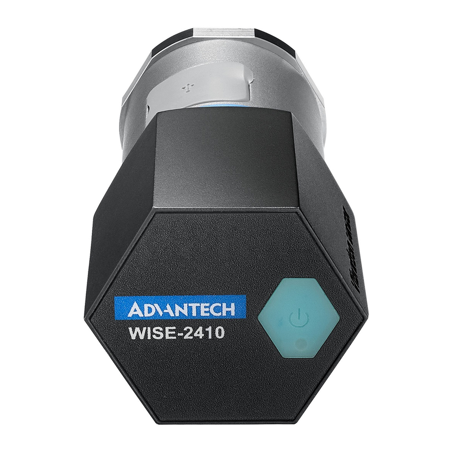
Page 15: Power
Power WISE-2410 is designed for two AA 3.6VDC batteries as an power source. Press the power switch on the top of chassis (see the Figure 1.3 led) and turn on WISE-2410. Note! Battery needs to order separately 1760002647-01 3.6V/2500mAh AA Cylindrical Battery (nonrecharge-... - Page 16 WISE-2410 User Manual...
-
Page 17: Chapter 3 Mechanical And Hardware Installation
Chapter Mechanical and Hardware Installation... -
Page 18: Interface Introduction
Interface Introduction Figure 3.1 WISE-2410 Interface Introduction Tighten two chassis Turn clockwise the top chassis to locking point to tighten bottom chassis. Figure 3.2 Tighten two chassis WISE-2410 User Manual... -
Page 19: Mounting
Applicable installation methods are briefly described in the following sections. 3.3.1 Installation Direction WISE-2410 Builds-in 3-axis vibration sensor. Please follow the following installation guide to make sure the eigenvalues from your device are correct. Figure 3.3 WISE-2410 Installation Direction on motor Figure 3.4 WISE-2410 Detail Installation Direction on motor... -
Page 20: Stud Mount
Wrench to fasten WISE-2410(with stud) to hold of motor. Figure 3.6 Stud mount 3.3.3 Magnetic bases To avoid the sudden impact damage WISE-2410, please follow the following steps. First, fasten magnetic base on the motor. Fasten WISE-2410 and magnetic base. Figure 3.7 Magnetic bases... -
Page 21: Adhesive Mounting Pad
3.3.4 Adhesive Mounting Pad Fasten WISE-2410 and stud, use adhesive epoxy glue(24hours) to stick on the motor surface. Figure 3.8 Adhesive Mounting Pad WISE-2410 User Manual... -
Page 22: Battery Replacement
Battery Replacement Slowly remove top chassis Figure 3.9 Battery Replacement Step1 Plug in new batteries and make sure the anode and cathode Figure 3.10 Battery Replacement Step 2 Figure 3.11 Battery Replacement Step 3 WISE-2410 User Manual... - Page 23 Plug in the battery pack and make sure the cable is hidden between the PCBA and the battery pack as follow. Figure 3.12 Battery Replacement Step 4 Figure 3.13 Battery Replacement Step5 WISE-2410 User Manual...
- Page 24 Figure 3.14 Battery Replacement Step6 WISE-2410 User Manual...
-
Page 25: Chapter 4 System Configuration
Chapter System Configuration... -
Page 26: Sensor And Gateway Connections
Connect the module to your computer via the micro-USB port. Execute WISE Studio. Clicking Go to Configuration while it shows "available USB-Serial" in USB- Serial box, press Go To Configuration. Click Connect to link the WISE-2410 and the web configuration page will appear. WISE-2410 User Manual... - Page 27 PC Browser Chrome Firefox IE11 IE10 Configuration File Upload Data Log Chart Data Log Export Click Information to check the basic information of the module. Click Configuration to use Information, RF Module, Time&Date, Scheduling, Control, Firmware settings. WISE-2410 User Manual...
-
Page 28: Lorawan Gateway (Wise-6610) Configuration
Click IO Status to check vibration and temperature data. 4.1.2 LoRaWAN gateway (WISE-6610) configuration Default IP of WISE-6610 is 192.168.1.1 Login- Username: root Password: root You can see the main page of Router; you can change IP in LAN if needed. WISE-2410 User Manual... - Page 29 LoRaWAN setting Step1: Choose User Modules and LoRaWAN Gateway. You can see WISE-6610N100-A (Support NA frequency band), make sure all of these parameters are matching with the RF module setting on WISE-2410. WISE-2410 User Manual...
- Page 30 If you want to know any items' description, you can refer WISE-6610 user manual. A new tab will pop-up after click on Network Server (http). Account: root Password: root WISE-2410 User Manual...
-
Page 31: Binding Process Between Wise-2410 And Wise-6610
4.1.3 Binding Process Between WISE-2410 and WISE-6610 This section will guide you to setup the connection between WISE-2410 and WISE- 6610. Enter the “Network Server (http)” in WISE-6610 gateway as follow. Create an end node device according the OTAA or ABP method. The following flow will use ABP mode for description the binding process. - Page 32 In this demo, a WISE-2410 is used. D. NwkSKey: the network service key address of an end node. Copy-pate “Networks Session Key” from WISE-2410 “RF module” tab. E. AppSKey: the application service key of an end node. Copy-pate “Networks Session Key” from WISE-2410 “RF module” tab.
- Page 33 Back to WISE-2410 configuration setting page. Click “Configuration” > “RF Mod- ule” and choose “LoRaWAN” for RF operation mode setting on WISE-2410. Create a “network server” gateway. Copy-paste the MAC address from “LoRaWAN radio” > “LoRaWAN Gateway Identifier”. Then click on “submit”.
- Page 34 WISE-2410 User Manual...
- Page 35 Arguments” input correctly. C. Users can also access into “Network Server (http)”. The “Received frames” page shows the received results. The “FCnt” shows the frame sequence. If this sequence is in-continuously, means some of the packets were lost. WISE-2410 User Manual...
-
Page 36: Wise-2410 Configuration
WISE-2410 Configuration All functions of WISE Studio for WISE-2410 is below: System Function Item Functional Description Display module name, Network status, Power status, Information Firmware version. Module Information RF related setting Date/time, time zone settings Configuration Schedule of when sensor should start mea- ... -
Page 37: Configuration
Information: Device identity and location settings RF Module: RF Related Settings Binding process between WISE-2410 and WISE-6610, please go to Section 4.1 for more details. For LoRaWAN parameter description, please check the docu- ment of "lorawan_regional_parameters" from LoRaWAN Alliance website. –... - Page 38 Scheduling: Data reports interval setting with optional weekly scheduling setting Based on application scenario, user can set scheduling of WISE-2410. – Mode: Basic/Advance – Day: Mask for Sunday ~ Saturday – Start time: 00: 00 ~ 23: 59 –...
-
Page 39: Io Status
Please select the channel for correspondent settings with each axis. 0 means X-axis. 1 means Y-axis. 2 means Z-axis. – If the sensing target vibrate abnormally and pass through a threshold, it can send alarm to LoRa gateway. WISE-2410 User Manual... - Page 40 Temperature alarm – Please select Channel 3 for Temperature sensor configuration. – If the sensing target temperature raise and pass through a threshold, WISE will send alarm to a gateway. WISE-2410 User Manual...
-
Page 41: Data Logger
By Channel: 0 means X-axis. 1 means Y-axis, 2 means Z-axis, 3 means Tem- perature. – By Sensor: Data from sensors, including vibration features, alarm trigger, sensor status and raw data. Logger Configuration: Enable or Disable the I/O log function WISE-2410 User Manual... - Page 42 – Timestamp: Local date and time (GMT) or Coordinated universal time (UTC) Query Filter – Filter Mode: User can choose No Filter Enable, Time Filter or Amount of Lat- est Data – Query result as follow WISE-2410 User Manual...
-
Page 43: Diagnostician
4.2.5 Diagnostician Display any errors detected by module. 4.2.6 Downlink Command For better user experience, WISE-2410 supports to config time and update interval remotely. Please contact local FAE for more detail technical supports. WISE-2410 User Manual... -
Page 44: Get Raw Data From Wise-2410
Get Raw Data from WISE-2410 For WISE-2410 series, there are two operation modes for querying vibration raw data: Standard mode and Real Time mode. Standard mode: User could query/get raw data which was previously measured and stored in WISE-2410. - Page 45 Recordt data could be exported as CSV file. Please select file folder and press “Export as CSV” to export records. Mark data: User could click “Mark Chart Point” to show real data as a “Red Dot” in the chart. WISE-2410 User Manual...
-
Page 46: Real-Time Operation Mode
In Real-Time operation mode, user could get real time raw data. Please check “Export as CSV” to export records before pressing “Start” button. Press “Start” button and there will be 3 charts (X, Y, Z axis) displayed in real time. Press “Stop” button to terminate data query. WISE-2410 User Manual... -
Page 47: Appendix A Modbus Address
Appendix Modbus Address... - Page 48 WISE-2410 (for WISE-6610 LoRaWAN GW) Sensor Temperature Sensor Acceleromter Axis Address 0X Description Attribute 00231 0 (X) Read Acceleromter 00232 1 (Y) Read High Alarm Flag 00233 2 (Z) Read 00234 3 (Temp) Temperature High Alarm Flag Read Address 4X...
- Page 49 0 (X) Read 40801 1 (Y) Standard deviation (0.01) Read 40802 2 (Z) Read 40803 0 (X) Read 40821 Peak-to-Peak 1 (Y) Read 40822 Displacement (μm) 2 (Z) Read 40823 WISE-2410 User Manual...
- Page 50 No part of this publication may be reproduced in any form or by any means, such as electronically, by photocopying, recording, or otherwise, without prior written permission of the publisher. All brand and product names are trademarks or registered trademarks of their respective companies. © Advantech Co., Ltd. 2020...
Need help?
Do you have a question about the WISE-2410 and is the answer not in the manual?
Questions and answers