Table of Contents
Advertisement
Quick Links
Advertisement
Table of Contents

Related Manuals for Lumens VC-A71P-HN


Summary of Contents for Lumens VC-A71P-HN
- Page 1 VC-A71P-HN PTZ Video Camera (4K PTZ Video Camera) User Manual - English Version VCBK100 To download the latest versions of the Quick Start Guide, multilingual user manual, software, driver, etc., please visit Lumens https://www.MyLumens.com/support...
-
Page 2: Table Of Contents
Table of Contents Chapter 1 Package Contents ..............3 Chapter 2 Function Introduction ............4 2.1 I/O functions Introduction .................. 4 2.2 Description of LED indicator ................6 2.3 Tally Lamp Function Description ............... 6 Chapter 3 Instruction for installation ............. 7 3.1 Camera Size ..................... -
Page 3: Chapter 1 Package Contents
Chapter 1 Package Contents Instruction for Camera Remote Control Installation AC Power Cord Power Adapter RS-422 Connector Appearance may vary depending on county/ region Metal Plate A Metal Plate B M3 Screws Silver x8/ Black x2... -
Page 4: Chapter 2 Function Introduction
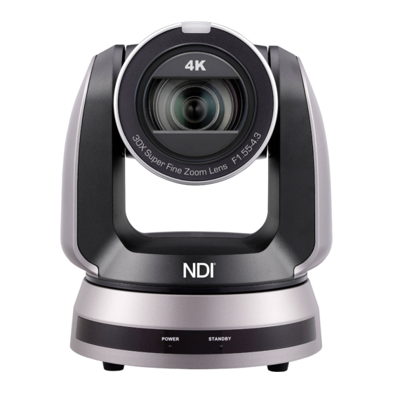
Chapter 2 Function Introduction 2.1 I/O functions Introduction 2.1.1 Front View ① ○ ○ Item Function Descriptions Tally Lamp Displaying the Tally Lamp status of the camera Camera lens 30x HD camera lens Power/Standby LED Displaying the status of the camera, please refer to indicator Description of LED indicator... - Page 5 2.1.2 Back View ④ ⑤ ⑥ ⑦ ⑨ ⑩ ⑧ ⑫ ⑪ ⑬ ⑭ ⑮ ⑯ ⑰ Item Function Descriptions Kensington lock Safety lock slot hole The remote control ID setting is only controlled after corresponding IR SELECT to the Camera Select on the remote control Network port supports routers or hubs of PoE++ (IEEE802.3bt) Network port with power supply...
-
Page 6: Description Of Led Indicator
2.1.3 Bottom ○ ○ ○ Item Function Descriptions The cooling fan automatically controls its rotation speed and Mute cooling fan performs cooling in cope with the operation temperature of the machine The camera is mounted on a (specification) 1/4”-20 UNC tripod Tripod lock hole When using the metal plates of accessories, remove 4 pieces of Rotatable foot pad... -
Page 7: Chapter 3 Instruction For Installation
Chapter 3 Instruction for installation 3.1 Camera Size 3.1.1 Camera Front View and Side View Length x Width x Height: 232 x 188 x 189 mm Weight: 3.0 Kg (without mental plates) 3.1.1.1 Camera Bottom View The camera can be mounted on a 1/4”-20 UNC PTZ tripod deck by using the lock holes on the bottom for the tripod... -
Page 8: Preparation Before Installation
3.2 Preparation before installation Installation and connection of HD camera requires special skills. To install by yourself, please follow necessary steps, ensure steady and tight installation of the device, and pay attention to your safety to avoid any accident. 3.2.1 Ensure the safety of the installation environment. Please do not install the device on unstable ceiling or in a place where the device is in danger of falling to avoid any accident. - Page 9 3.3.2.2 Metal Plate size diagram Metal plate A - machine side Metal plate A locking screw Metal plate A - machine side...
- Page 10 Metal plate B - ceiling side Metal plate B locking screw Metal plate B locking bolt M3 threaded hole M3 threaded hole M3 threaded hole Metal plate B - ceiling side...
- Page 11 3.3.2.3 Precautions for installation 1. Before installation, please confirm the orientation of the machine relative to the object to be captured 2. It is recommended that the machine should be set at a distance of more than 1.5 meter away from the object to be captured. Please adjust for a best distance according to the magnification of the lens Projector 1.5 meter ↑...
- Page 12 2. Fix the metal plate A on the machine base with 4 M3 silver screws 3. Lock the metal plate B on ceiling mounted hanger <Note> (1) Please use the hanger that has obtained UL security approval (2) Please reserve the hole for the connecting wires of the camera 4.
-
Page 13: Connecting Devices
A and B and push to the left to remove the machine 3. Then remove the screws on the hanger and the machine 3.4 Connecting devices 3.4.1 RS-232 Connection With RS-232 in/out, at most 7 Lumens cameras can be connected. RS-232 pins definition instructions... - Page 14 3.4.2 RS-422 Connection With RS-422, at most 7 Lumens cameras can be connected. <Note> When RS-422 connection is being used, do not use RS-232 connection. RS-422 pins definition instructions...
- Page 15 RS-422 connection instructions 1. Hold the two sides of RS-422 connector and pull out in the direction shown by the arrow in the figure below 2. Peel off a section of copper wire (AWG Nos. 28 to 18) and insert it into the connector hole;...
-
Page 16: Chapter 4 Remote Control And Setting Menu
Chapter 4 Remote Control and Setting Menu 4.1 Functions of remote control Item Description ➊ Power Power Switch ➓ Numeric Keys 0 - 9: Click to call the preset Preset: Appoint an ID (0 ~ 9) to save the ➋... -
Page 17: Setting Menu
4.2 Setting Menu <Remark> Press [MENU] on the remote control to enter the setting menu; the bold underlined values in the following table are defaults. Level Level Level Function Descriptions Major Items Minor Items Adjustment Values 1. Full Auto 2. Shutter Pri Mode Exposure mode setting 3. - Page 18 Level Level Level Function Descriptions Major Items Minor Items Adjustment Values Adjustable when the Image mode 0~C~15 is set to Custom Adjustable when the Image mode Saturation 0~C ~15 is set to Custom Adjustable when the Image mode Gamma 0~C~3 is set to Custom Pan/Tilt Limit On / Off...
- Page 19 Level Level Level Function Descriptions Major Items Minor Items Adjustment Values Press [ENTER] to be in modify mode; select the item to be modified using the up and down IP Address 192.168.100.100 keys, and modify the value using the left and right keys or the numeric keys.
- Page 20 Level Level Level Function Descriptions Major Items Minor Items Adjustment Values Link: When the indicator light is on, the default mode is red light Setting the indicator light mode when the indicator light is off will turn on the indicator light Language English / Chinese Select the camera lens to return to...
-
Page 21: Chapter 5 Network Function Settings Description
Chapter 5 Network Function Settings Description 5.1 Connecting Camera to Network 5.1.1 Connecting to Internet Two common connection methods are shown below 1. Connecting via switch or router Network cable Network cable Camera Switch or router Computer 2. To connect directly through network cable, the IP address of the computer should be changed so that it is on the same network segment as the camera E.g.: The factory-preset default IP address of the camera is 192.168.100.100. - Page 22 <Remark> Supported when NDI|HX function is off (Please refer to 5.2.5 Streaming - NDI) Open LUMENS VMS software (Please download from the Lumens official website) Search Camera: Press [automatically search for the device] button to locate the Camera ...
- Page 23 RTSP connection address formats are as follows: RTSP Main Streaming (4K@H.265)=> rtsp://camera IP:8554/hevc RTSP Sub1 Streaming (1080P@H.264)=> rtsp://camera IP:8557/h264 RTSP Sub2 Streaming (720P@H.264)=> rtsp://camera IP:8556/h264 If password authentication is enabled, the RTSP connection address is as follows: ...
-
Page 24: Web Page Function Description
5.2 Web Page Function Description 5.2.1 Live View <Remark> The preview window is not supported when NDI|HX is on 9 10 11 NDI|HX NDO|HX Item Function Descriptions Display camera ID/location Camera ID/ location Please refer to 5.2.7 System Settings - Device Display the screen currently captured by Preview window... - Page 25 5.2.2 Camera Setting Item Function Descriptions Mode: Select exposure mode (Full Auto / Shutter Pri / Iris Pri / Manual) Gain Level: Adjust the gain level (adjustable under the “Manual”) WDR: Set the level of wide dynamic range (WDR) in order to obtain better images Exposure ...
- Page 26 Pan/Tilt limit: Enable, and set the pan/tilt limit Pan/Tilt flip: When it is set, the Pan/Tilt direction will go oppositely Preset Speed: Set the rotation speed of the cradle head when Preset is executed PTZ Speed Comp: After it is activated, the Pan/Tilt moving speed will vary from the zoom position ...
- Page 27 5.2.3 Audio NDI|HX NDI|HX Item Function Descriptions Audio Enable Enable/disable audio Audio In Set MIC In/Line In Encode Type AAC / G.711 Set Encode sample rate 48 KHz (AAC) 44.1 KHz (AAC) Encode Sample Rate 16 KHz (AAC) ...
- Page 28 5.2.4 Stream <Remark> The setting is available when NDI|HX is on Item Function Descriptions Stream Support types: MPEG-TS/RTMP/RTMPS/RTSP/SRT Type Enable/Disable Multicast <Remark> It is suggested to enable Multicast when the number of users online watching the image simultaneously is more than 4 ...
- Page 29 MPEG-TS Set MPEG-TS format <Remark> Port must be set in the range above 1024 with a maximum value of 9999 <Remark> The following port is used by the camera. Setting of the port may not connect correctly 8557, 8556, 8555, 1935 ...
- Page 30 The port number must be set in the range above 1024 with a maximum value of 9999 <Remark> The following port is used by the camera. Setting of the port may not connect correctly 8554, 8557, 8556, 8555, 19353 ...
- Page 31 5.2.5 Streaming - NDI <Remark> The setting is available when NDI|HX is on Item Function Descriptions Camera ID/ Location Displaying ID/location according to [System Settings] > [Device] setting content The group name can be modified here and set with Access Manager - Receive in NDI Tool ...
- Page 32 5.2.6 Streaming - High Bandwidth NDI Item Function Descriptions On / Off Enable / Disable High Bandwidth NDI Camera ID Displaying ID according to [System Settings] > [Device] setting content Modify the location of the camera, such as Room 1 ...
- Page 33 5.2.7 System Device - Device Item Function Descriptions Change camera ID here Camera IDs are limited to 1 - 12 characters Please mix uppercase and lowercase letters or numbers for characters. Camera ID Special symbols such as “/” and “space” cannot be used <Remark>...
- Page 34 5.2.8 Setting - Audio Item Function Descriptions Set the resolution of the camera Resolution After switching the resolution, the camera will restart. Please refresh the browser According to the output protocol, you can select HDMI + Streaming, HDMI+NDI or HDMI + UVC output Output Source <Remark>...
- Page 35 5.2.9 Setting - Network Item Function Descriptions Network setting of camera. Change of setting is available when DHCP DHCP function is closed HTTP port Set HTTP port. The default Port value is 80 HTTPS port Set HTTPS port. The default Port value is 81 Tracking Data Output When enabled, PTZ position information can be reported when the camera moves...
- Page 36 5.2.10 Setting - Maintenance - Security Function Descriptions Enable/disable 802.1x protocol, and configure settings when enabled <Remark> The router must support 802.1x protocol to enable this feature 5.2.11 Settings - Date & Time Function Descriptions Display date and time of the current camera/ PC. You may set the synchronization method and modify date and time...
- Page 37 5.2.12 Settings - User Function Descriptions Add/ Modify/ Delete user account Supporting 4 ~ 32 characters for user name and password Please mix uppercase and lowercase letters or numbers for characters. Special symbols or the underlined cannot be used ...
- Page 38 Settings – Control Port Number 5.2.13 Item Function Descriptions Control Port RS-232 / RS-422 Baud Rate Choose the transmission speed of the control signal as 9600/38400 Protocol VISCA/Pelco D protocol is supported VISCA address The camera ID address 0 ~ 7 can be assigned. Pelco D address The camera ID address 1 ~ 255 can be assigned.
- Page 39 5.2.14 Maintenance Item Function Descriptions Click the link to check the lastest firmware. Click [….] to select the firmware file, and click [Upgrade] to update the firmware Firmware Update <Remark> Update takes about 2 - 3 minutes <Remark> Please do not operate or turn off the power of the device during the update to avoid firmware update failure Factory Reset Restore the factory default setting...
- Page 40 5.2.16 About Function Descriptions Display the firmware version, serial number, running time and other related information of the camera For technical support, please scan the QRcode at the bottom right...
-
Page 41: Chapter 6 Dip Switch Setting
Chapter 6 DIP Switch Setting 6.1 DIP SWITCH 6.1.1 OUTPUT Switch (Switch to different output resolutions) To switch via the OSD/ Web Page/RS-232 Command is also available based on the last executed action Output Frame Rate Note Resolution <Remark> For 3G-SDI, 59.94 1080P output will be automatically... -
Page 42: Chapter 7 Troubleshooting
Chapter 7 Troubleshooting This chapter describes problems you may encounter while using VC-A71P-HN. If you have questions, please refer to related chapters and follow all the suggested solutions. If the problem still occurred, please contact your distributor or the service center. -
Page 43: Chapter 8 Safety Instructions
Chapter 8 Safety Instructions Always follow these safety instructions when setting up and using the VC-A71P-HN PTZ Video Camera: 1 Operation 1.1 Please use the product in the recommended operating environment, away from water or source of heat 1.2 Do not place the product on a tilted or unstable trolley, stand or table. - Page 44 Supplier's Declaration of Conformity 47 CFR § 2.1077 Compliance Information Manufacturer:Lumens Digital Optics Inc. Product Name:VC-A71P-HN Model Number:PTZ Video Camera Responsible Party – U.S. Contact Information Supplier:Lumens Integration, Inc. 4116 Clipper Court, Fremont, CA 94538, United States e-mail :support@mylumens.com FCC Compliance Statement This device complies with Part 15 of the FCC Rules.
-
Page 45: Copyright Information
Lumens is a trademark that is currently being registered by Lumens Digital Optics Inc. Copying, reproducing or transmitting this file is not allowed if a license is not provided by Lumens Digital Optics Inc. unless copying this file is for the purpose of backup after purchasing this product.
Need help?
Do you have a question about the VC-A71P-HN and is the answer not in the manual?
Questions and answers