Table of Contents

Related Manuals for Lumens VC-A70HB


Summary of Contents for Lumens VC-A70HB
- Page 1 VC-A70H (PTZ Video Camera) Installation Guide - English [Important] To download the latest version of Quick Start Guide, multilingual user manual, software, or driver, etc., please visit Lumens https://www.MyLumens.com/support...
-
Page 2: Table Of Contents
Table of Contents Copyright Information ....................3 Chapter 1 Safety Instructions ..................4 Chapter 2 Package Contents ..................7 Chapter 3 Product Overview ..................8 Overview ..................... 8 Description of LED indicator ............... 8 Chapter 4 Instruction for installation ................9 Preparation before installation ............ - Page 3 6.11 I would like to adjust the AF speed ........... 31 6.12 I would like to set the image mode ........... 32 6.13 I would like to freeze images ............32 6.14 I would like to rotate the image ............32 6.15 I would like to change the camera direction ........
-
Page 4: Copyright Information
Lumens is a trademark that is currently being registered by Lumens Digital Optics Inc. Copying, reproducing or transmitting this file is not allowed if a license is not provided by Lumens Digital Optics Inc. unless copying this file is for the purpose of backup after purchasing this product. -
Page 5: Chapter 1 Safety Instructions
Chapter 1 Safety Instructions Always follow these safety instructions when setting up and using the PTZ Video Camera: 1 Operation 1.1 Please use the product in the recommended operating environment. 1.2 Do not place the product in tilted position. 1.3 Do not place the product on an unstable trolley, stand or table. 1.4 Do not use this product near water or source of heat. - Page 6 Precautions Warning: To reduce the risk of fire or electric shock, do not expose this appliance to rain or moisture. Unplug this product during thunderstorms or if it is not going to be used for an extended period. Note Risk of Electric ShockPlease do not open it by yourself Caution: To reduce the risk of electric shock, do not remove cover (or back).
- Page 7 Extron IP Link Compatible Extron has developed and tested an IP Link driver for this product. Using IP Link technology, this device can be monitored, controlled and supported over a standard Ethernet network. In order to enable IP Link network connectivity and control, you must install and configure an IP Link-enabled device such as a MediaLink controller or IP Link Ethernet control interface.
-
Page 8: Chapter 2 Package Contents
Chapter 2 Package Contents VC-A70H Instruction for installation Remote Control Power Cord Power Adapter RS-422 Connector Appearance may vary depending on country/region Metal Plate A Metal Plate B M3 Screws English... -
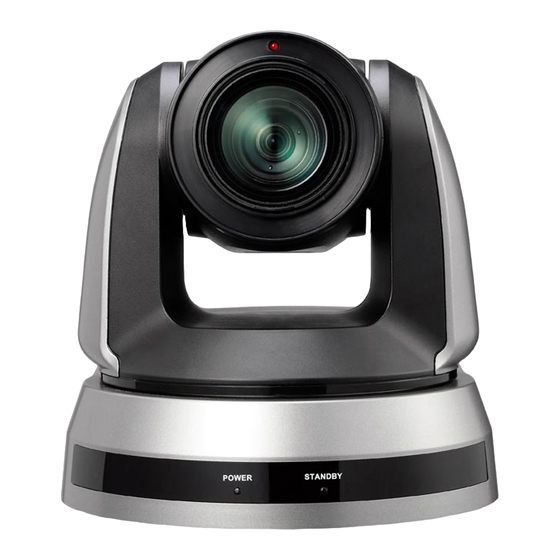
Page 9: Chapter 3 Product Overview
Chapter 3 Product Overview 3.1 Overview Back View Front View 1. Tally indicator 2. Camera lens 3. Power LED indicator 4. Standby LED indicator 5. HDBaseT output 6. Power input 7. IR SELECT 8. OUTPUT Switch 9. Camera Address Selectors 10. -
Page 10: Chapter 4 Instruction For Installation
Chapter 4 Instruction for installation 4.1 Preparation before installation Installation and connection of VC-A70H PTZ Video Camera requires special skills. To install by yourself, please follow necessary steps, ensure steady and tight installation of the device, and pay attention to your safety to avoid any accident. 4.1.1 Ensure the safety of the installation environment. - Page 11 4.2.1.2 Installation steps 1. Please adjust DIP switch at first prior to installation <Remark> Please refer to Chapter 7 DIP Switch Setting for the relevant descriptions on DIP switch. 2. Place the camera on a flat desk directly to ensure the normal vertical and horizontal operation of the machine I would like to install VC-A70H on the ceiling 4.2.2...
- Page 12 4.2.2.2 Camera Size Length x Width x Height : 174 x 186.8 x 170.8 mm Weight : 2.0 Kg 4.2.2.3 Max. rotation dimension of camera English...
- Page 13 4.2.2.4 Size Diagram 1. Metal plate B - ceiling side Metal plate B locking Metal plate B locking bolt screw English...
- Page 14 M3 threaded hole M3 threaded M3 threaded hole hole Metal plate B - ceiling side English...
- Page 15 2. Metal plate A - machine side Metal plate A locking screw Metal plate A - machine side English...
- Page 16 3. Bottom of machine English...
- Page 17 4.2.2.5 Precautions for installation 1. Before installation, please confirm the orientation of the machine relative to the object to be captured 2. It is recommended that the machine should be set at a distance of more than 1 meter away from the object to be captured. Please adjust for a best distance according to the magnification of the lens 1 meter↑...
- Page 18 3. Lock the metal plate B on ceiling mounted hanger ※Caution: (1) Please use the hanger that has obtained UL security approval (2) Please reserve the hole for the connecting wires of the camera 4. Combine the metal plate A and the metal plate B (1) Push the metal plate A up to the ceiling and then to the right to latch the metal plate B (2) And then secure with 2 M3 silver screws and 1 M3 black screw.
- Page 19 black screw 4.2.2.7 How to remove 1. Remove the connecting wires from the camera 2. Uninstall the camera together with the ceiling, loosen the three screws that fix the metal plates A and B and push to the left to remove the machine 3.
-
Page 20: Connecting The Device
4.3 Connecting the device 4.3.1 Image Output Connecting to an HDTV/computer monitor (HDMI) 4.3.1.1 HDMI Cable Monitor or HDTV Connecting to a HDBaseT Adapter 4.3.1.2 HDBaseT Cable HDBaseT Adapter * PoE Power Supply is available for this device. HDBaseT Adapter may be enabled without connecting to a power cord English... - Page 21 4.3.2 Controlling VCs with the computer Connecting to one computer for connection between VCs 4.3.2.1 (RS-232 in/out) <Remark> With RS-232 in/out, at most 7 VCs can be connected. Connecting to one computer for connection between VCs 4.3.2.2 (RS-422) <Remark> Please refer to 7.2 RS-422 connection for the RS-422 connection instructions.
-
Page 22: Chapter 5 Remote Control And Setting Menu
Chapter 5 Remote Control and Setting Menu 5.1 Functions of remote control <Remark> The below functions are listed alphabetically. Item Description ,,, Move the lens Back Light Turn on/off back light compensation Camera Select 1 ~ 3 VC-A70H select Focus- Turn on manual focus to adjust the focal Manual / length... -
Page 23: Setting Menu
5.2 Setting Menu <Remark> Press [Menu] on the remote control to enter the setting menu; the bold underlined values in the following table are defaults. Level Level Level Adjustment Major Function Descriptions Minor Items Values Items 1. Full Auto 2. Brightness Mode 3. - Page 24 1/125 1/120 1/100 1/100 1/90 1/75 1/60 1/50 1/30 1/25 1/15 1/12 F1.8 F2.4 F2.8 F3.4 F4.8 Iris Pri Iris setting F5.6 F6.8 10. F8 11. F9.6 12. F11 13. F14 14. Close English...
- Page 25 3 dB 6 dB 9 dB 12 dB 15 dB Manual Gain Manually set the gain 18 dB 21 dB 24 dB 10. 27 dB 11. 30 dB 12. 33 dB 59.94/29. 50/25 97 mode mode 1/10000 1/10000 1/6000 1/6000 1/4000 1/3500 1/3000...
- Page 26 F1.8 F2.4 F2.8 F3.4 F4.8 Manual Iris Manually set the aperture F5.6 F6.8 10. F8 11. F9.6 12. F11 13. F14 14. Close 1~ C~28 Bright 9 dB 12 dB 15 dB 18 dB Max. limit value of electron 21 dB Gain Limit gain 24 dB...
- Page 27 Auto Indoor Outdoor Trigger White Balance Auto White Balance Select the color temperature Mode Manual mode Outdoor Auto Sodium Lamp White Auto Balance Sodium Lamp 10. Sodium Lamp Outdoor Auto One Push ENTER One push trigger Trigger Adjustable when the white balance mode is set to R-Gain 0~ C~255...
- Page 28 Adjustable when the image 1. 1 Gamma mode is set to Custom 2. 2 mode Turn on/off the angle limit Pan / Tilt Limit On / Off setting Pan Right 0~170 Limit the right angle Limit Pan Left Limit -170~0 Limit the left angle Pan Tilt Tilt UP Limit...
- Page 29 When the function is enabled, the screen will Motionless Freeze when Preset is On / Off executed. Freeze will be Preset released after Preset is completed Turn on to reduce image On / Off Low Latency delay 1. Off 2. Clear Image Set the image zoom Digital Zoom Zoom...
-
Page 30: Chapter 6 Descriptions Of Major Functions
Chapter 6 Descriptions of Major Functions 6.1 I would like to switch to VC-A70H 1. Press [Camera 1 ~ 3] on the remote control to select VC-A70H. Camera 1 ~ 3 is selected with IR SELECT. 6.2 I would like to set the Digital Output (RGB, YUV) 1. -
Page 31: I Would Like To Save The Current Lens Position Data
5. Press [ENTER] to activate. 6. Press [] or [] to select [Off / On]. 7. Press [MENU] to exit. 6.5 I would like to save the current lens position data 8. Press [Preset + ID] on the remote control to save the current position data. ... -
Page 32: I Would Like To Adjust The Focal Length
6.9.2 Fine-tune image size Press [Slow +] on the remote control to zoom in images. Press [Slow -] on the remote control to zoom out images. 6.10 I would like to adjust the focal length 6.10.1 Auto tune Press [AF] on the remote control to adjust automatically. 6.10.2 Manual focus Press [MF] on the remote control to turn on the manual focus function. -
Page 33: I Would Like To Set The Image Mode
[Fast]: Fast focus speed Press [MENU] to activate the setting menu. Press [] or [] to select [Auto Focus]. Press [ENTER] to activate. Press [] or [] to select [AF speed]. Press [ENTER] to activate. Press [] or [] to select [Fast / Normal]. Press [MENU] to exit. - Page 34 Press [] or [] to select [On]. Press [ENTER] to execute. English...
-
Page 35: Chapter 7 Dip Switch Setting
Chapter 7 DIP Switch Setting <Note> Please turn off the machine before changing DIP switch setting. 7.1 DIP SWITCH 7.1.1 OUTPUT Switch Output Mode Setting Output Mode Setting 3840 × 2160 29.97p 3840 × 2160 25p 1920 × 1080 59.94p 1920 ×... - Page 36 7.1.2 IR SELECT Setting 7.1.3 Camera Address Selector Setting Function Descriptions ID 0~7 Reserved 7.1.4 System Switch Setting Function Descriptions RS-232C/RS-422 selector DIP 1 OFF : RS-232C / ON : RS-422 Infrared signal output switch DIP 2 OFF : Off / ON : On Communication baud rate selector DIP 3 OFF : 9600 / ON : 38400...
-
Page 37: Rs-422 Connection
7.2 RS-422 Connection 7.2.1 RS-422 Pin Description Pin NO. Function RXD OUT - RXD OUT + TXD OUT - TXD OUT + RXD IN - RXD IN + TXD IN - TXD IN + <Note> Please connect IN+ to OUT+ when connecting to SONY products For non-SONY products, it may be necessary to connect IN+ to OUT- 7.2.2 Use RS-422 Connection 1. - Page 38 2. Peel off a section of copper wire (AWG Nos. 28 to 18) and insert it into the connector hole; then use flat screw driver to fix it 3. Insert the wired RS-422 connector back to the camera. Now the connection is completed <Note>...
-
Page 39: Chapter 8 Troubleshooting
Chapter 8 Troubleshooting This chapter describes problems you may encounter while using VC-A70H. If you have questions, please refer to related chapters and follow all the suggested solutions. If the problem still occurred, please contact our distributors or service center. Problems Solutions Boot without power... - Page 40 The device cannot 1. Make sure the connection is correct (RS-232/422 Input). be controlled with 2. Make sure System Switch DIP 1 and DIP 3 are correct. RS-232/RS422 English...
-
Page 41: Information
Supplier's Declaration of Conformity 47 CFR § 2.1077 Compliance Information Manufacturer:Lumens Digital Optics Inc. Product Name:VC-A70H Model Number:PTZ Video Camera Responsible Party – U.S. Contact Information Supplier:Lumens Integration, Inc. 4116 Clipper Court, Fremont, CA 94538, United States :support@mylumens.com e-mail FCC Compliance Statement This device complies with Part 15 of the FCC Rules.
Need help?
Do you have a question about the VC-A70HB and is the answer not in the manual?
Questions and answers