Table of Contents
Advertisement
Quick Links
Advertisement
Table of Contents

Subscribe to Our Youtube Channel
Related Manuals for IFM MVQ101


Summary of Contents for IFM MVQ101
- Page 1 Device manual Valve sensor MVQ101...
-
Page 2: Preliminary Note
1 Preliminary note Technical data, approvals, accessories and further information at www.ifm.com. 2 Safety instructions • Read this document before setting up the product and keep it during the entire service life. • The product must be suitable for the corresponding applications and environmental conditions without any restrictions. -
Page 3: Functions And Features
3 Functions and features With this unit angular movements and positions of the valve between 0°...179.9° and -180°...0° can be determined. The unit generates output signals according to the operating mode and the parameter setting. 4 Installation ► Disconnect power before installation. ►... -
Page 4: Electrical Connection
5 Electrical connection ► Disconnect the installation from power and connect the unit. 2: OUT 2 4: OUT 1 / IO-Link 5: OUT 3 5.1 Switching functions OUT1 (pin 4) Communication IO-Link Switching output valve position open in SIO mode OUT 2 (pin 2) Switching output valve position closed OUT 3 (pin 5) -
Page 5: Operating And Display Elements
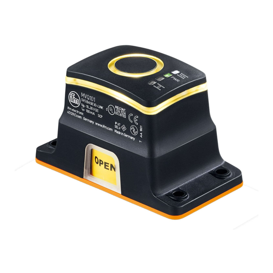
7 Operating and display elements LED 1 LED 5 LED PWR LED 3 LED 4 LED 5 1: Window for optical position indication (OPEN) 2: Inductive teach button LED 1 yellow on switching status OUT1 – valve position open LED 2 PWR green on voltage applied to the unit LED 3 not used... -
Page 6: Parameter Setting
► Connect the unit via the IO-Link interface to a PC or PLC with suitable parameter setting software. ifm offers an IO-Link interface for the connection of the sensor via USB port. 9.2 Setting parameters via IO-Link... - Page 7 Power cycles Number of switching opera- 0...2147483647 tions since delivery Operating hours Operating hours counter since 0...2147483647 delivery Valve offset Installation offset of the valve -180.0°...179.9° Steps 0.1° SSC1 and SSC2 Swap switch point Swap switch points Leak warning range Setting of the leak warning 0.0...15°...
- Page 8 Lock unit ► Activate teach button (approx. 20 s) until the LED ring briefly flashes once. > Unit is locked, no parameter setting possible. Unlock unit ► Activate teach button (approx. 20 s) until the LED ring briefly flashes once. 10 Settings Settings tolerance Set a tolerance range between 0.1°...
- Page 9 Setting leak warning range In the closed position SSC2, the unit features leak monitoring in the range from 0.0° to 15°. Deposits or wear can be detected. This leak warning range lies within the tolerance range and is activated and defined by selecting a value (>0) which is deduced from the tolerance range limits.
- Page 10 10.3 Parameter setting pin 5 Pin 5 of the sensor can have different functions: 1. Switching output valve position open 2. Switching output valve position closed 3. Switching output seat position 4. Fault output - Defect of the unit - Puck not used - Limit value for the timeout exceeded 10.4 Opening / closing duration The minimum/maximum closing/opening duration of the drive can be freely set...
Need help?
Do you have a question about the MVQ101 and is the answer not in the manual?
Questions and answers