Table of Contents
Advertisement
Quick Links
UG2020-30
REF-AIRCON-C302A-IM564 user guide
Air conditioner application reference design kits
About this document
Scope and purpose
This user guide provides an overview of the reference board REF-AIRCON-C302A-IM564 including its main
features, key test results and mechanical dimensions.
The REF-AIRCON-C302A-IM564 is a full-featured starter kit, turnkey motor drive designed for high-performance,
high-efficiency permanent magnet synchronous motor (PMSM) drive applications, including all of the required
elements for air conditioner applications, such as IMC302A iMOTION
PFC-integrated CIPOS
The starter kit features and demonstrates Infineon's CIPOS
(MCE 2.0) technology for PMSM/BLDC motor and PFC driver up to a rating of 600 V and 20 A. It is optimized for
major home appliances like air conditioner compressors, fans, pumps and other motor drive applications.
Note:
Please note that this product is not qualified according to the AEC Q100 or AEC Q101 documents of
the Automotive Electronics Council.
Intended audience
This application note is intended for all technical specialists who are familiar with air conditioner control and
electronics converters. The reference design is intended to be used under laboratory conditions only by trained
specialists.
Reference board
The Infineon products are embedded on this PCB with functions and form factor close to a commercial design.
PCB and auxiliary circuits are optimized for the final design.
Note:
Boards do not necessarily meet safety, EMI, quality standards (for example UL, CE) requirements.
User guide
www.infineon.com
Mini IPM IM564-X6D.
TM
Please read the Important notice and the Safety precautions and the Warnings
controller, 1ED44175 PFC gate driver and
TM
Mini IPM and advanced motion control engine
TM
page 1 of 45
V 1.0.1
2021-01-27
Advertisement
Table of Contents

Related Manuals for Infineon REF-AIRCON-C302A-IM564


Summary of Contents for Infineon REF-AIRCON-C302A-IM564
-
Page 1: About This Document
The reference design is intended to be used under laboratory conditions only by trained specialists. Reference board The Infineon products are embedded on this PCB with functions and form factor close to a commercial design. PCB and auxiliary circuits are optimized for the final design. Note: Boards do not necessarily meet safety, EMI, quality standards (for example UL, CE) requirements. -
Page 2: Important Notice
Boards provided by Infineon Technologies. The design of the Evaluation Boards and Reference Boards has been tested by Infineon Technologies only as described in this document. The design is not qualified in terms of safety requirements, manufacturing and operation over the entire operating temperature range or lifetime. -
Page 3: Safety Precautions
REF-AIRCON-C302A-IM564 user guide Air conditioner application reference design kits Safety precautions Safety precautions Please note the following warnings regarding the hazards associated with development systems. Table 1 Safety precautions Warning: The DC link potential of this board is up to 400 V . -
Page 4: Table Of Contents
Block diagram ............................5 Main features ............................7 Board parameters and technical data ....................7 System and functional description ................... 9 Getting started with REF-AIRCON-C302A-IM564 ..................9 Description of the functional blocks ..................... 15 2.2.1 Overview of IMC302A ........................15 2.2.2... -
Page 5: The Board At A Glance
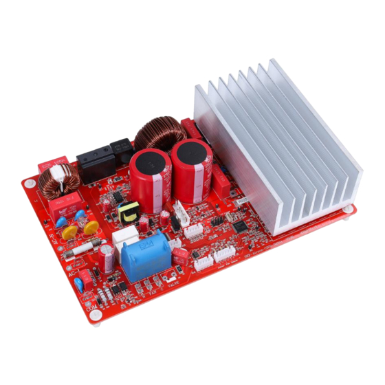
It is available through regular Infineon distribution partners as well as on Infineon's website. The main features of this board are described in this document, whereas the remaining paragraphs provide information to enable the customers to copy and modify the design for production according to their own specific requirements. - Page 6 REF-AIRCON-C302A-IM564 user guide Air conditioner application reference design kits The board at a glance Figure 2 points out the functional groups on the top side of the REF-AIRCON-C302A-IM564 reference design: 1. 220 V & PE input connector 10. AC fan and 4-way valve relay control 2.
-
Page 7: Main Features
Air conditioner application reference design kits The board at a glance Main features The REF-AIRCON-C302A-IM564 board is an optimized reference design for 220 V air conditioner applications, which contains iMOTION™ controller IMC302A, 20 A, 600 V PFC-integrated CIPOS™ Mini IPM and 1ED44175 PFC gate driver. - Page 8 REF-AIRCON-C302A-IM564 user guide Air conditioner application reference design kits The board at a glance Parameter Symbol Conditions / comments Value Unit Current feedback PFC shunt resistance 5 W shunt resistor with external OPA gain 14.7 mΩ Motor shunt resistance Direct AD sample (without external OPA) mΩ...
-
Page 9: System And Functional Description
After downloading and installing the iMOTION™ PC tools, MCEWizard and MCEDesigner, the following steps need to be executed in order to run the motor. Refer to MCEWizard and MCEDesigner documentation for more information. Figure 3 shows the basic system connection using REF-AIRCON-C302A-IM564 to run motor with MCEDesigner: Motor Phase Outputs... - Page 10 REF-AIRCON-C302A-IM564 user guide Air conditioner application reference design kits System and functional description Figure 4 shows the MCEWizard welcome page and interface of MCEDesigner. MCEWizard welcome page and MCEDesigner interface Figure 4 User guide 10 of 45 V 1.0.1 2021-01-27...
- Page 11 (IMC302A_Vxxx.irc) by clicking “File” > “Open”. (IMC302A_Vxxx.irc file is included in downloaded “IMC302A MCE Software Package”) MCEDesigner should automatically connect to the REF-AIRCON-C302A-IM564 board using default COM port (Indicated by green circle next to “COMx Up” status in the bottom frame of the MCEDesigner GUI).
- Page 12 REF-AIRCON-C302A-IM564 user guide Air conditioner application reference design kits System and functional description If it cannot establish the connection due to incorrect COM port, change COM port by doing the following: Click on the “System Page” window and then click on “Preferences > Connection > Connect using” and choose one of the other available COM ports from the drop-down list.
- Page 13 REF-AIRCON-C302A-IM564 user guide Air conditioner application reference design kits System and functional description 9. Double click the “VF Diagnostic” function in Motor1 page, and monitor the motor current with oscilloscope. If the motor current is not sinusoidal, change the target speed and Vd_Ext in VF Diagnostic sub-function, then double-click “VF Diagnostic”...
- Page 14 REF-AIRCON-C302A-IM564 user guide Air conditioner application reference design kits System and functional description Trace waveform for Iu & Flx-M at 50% speed Figure 9 13. Once the firmware has been programmed, in case a new parameters’ file has to be programmed, follow the same instructions given in step 9.
-
Page 15: Description Of The Functional Blocks
System and functional description Description of the functional blocks The motor inverter and PFC convertor of the REF-AIRCON-C302A-IM564 reference design are implemented by the IM564-X6D IPM module, and the PFC MOSFET gate driver is 1ED44175. The control functions of the air conditioning system, motor and PFC are implemented by IMC302A. -
Page 16: Overview Of Im564-X6D
REF-AIRCON-C302A-IM564 user guide Air conditioner application reference design kits System and functional description Integrated analog comparators for overcurrent protection Integrated scripting engine for application flexibility Flexible host interface options for speed commands: UART, SPI, PWM or analog signal ... - Page 17 REF-AIRCON-C302A-IM564 user guide Air conditioner application reference design kits System and functional description Block diagram of IM564-X6D Figure 11 The IM564-X6D is in DIP 36x21D package; the pin definition and package outline are shown in Figure 12. Figure 12 IM564-X6D lead assignments...
-
Page 18: Overview Of 1Ed44175
REF-AIRCON-C302A-IM564 user guide Air conditioner application reference design kits System and functional description 2.2.3 Overview of 1ED44175 A 1ED44175 is used for the PFC MOSFET drive and PFC OCP, its main functions and features are as follows: 2.6 A low-side driver with overcurrent protection and fault/enable pin ... -
Page 19: Overview Of Ice5Ar4770Bzs
Air conditioner application reference design kits System and functional description 2.2.4 Overview of ICE5AR4770BZS The ICE5AR4770BZS is Infineon’s latest (5 generation) fixed-frequency CoolSET offering high performance and integration of the latest generation of 700 V CoolMOS superjunction MOSFETs in DIP-7 packages. -
Page 20: Design Tips For Direct Motor Current Sensing
Current feedback scaling outside IMC302A Direct AD sample is used in the motor section of REF-AIRCON-C302A-IM564 reference design, i.e., motor current sensing is done without an external OPA (Only C51, R83 & R77 used for operational gain, bias and low pass filter), as shown in Figure 16. - Page 21 REF-AIRCON-C302A-IM564 user guide Air conditioner application reference design kits System and functional description R77 & R83 also determine the 49 mV ADC operational bias for current sensing, which corresponds to the motor regeneration operation range. For air conditioner applications and other applications that only work in motoring mode, the bias can be as low as possible to reserve enough ADC range for the motoring mode, since negative current sensing would not occur.
-
Page 22: Design Tips For Pfc Current Sensing
As mentioned in the motor current sensing section, common mode noise rejection (CMR) is vitally important for direct current AD sample. The PFC current sensing shunt resistor is located at a long distance from the IMC302A IC in the REF-AIRCON-C302A-IM564 board, i.e. PFC current sensing cannot use the direct AD sample mode any more. - Page 23 Air conditioner application reference design kits System and functional description Figure 19 shows the external amplifier gain circuit in the REF-AIRCON-C302A-IM564 reference design, which is a typical differential amplifier, with input LPF and operational bias. C24, R43, R52, R58, R59 build the input differential mode LPF, which can damp part of the PWM switching noise.
-
Page 24: System Design
System design System design The REF-AIRCON-C302A-IM564 board is an optimized design for 220 V major home appliances like air conditioner applications. To meet individual customer requirements and to make the REF-AIRCON-C302A- IM564 reference design a basis for development or modification, all board design data such as schematics, Gerber and Altium design data can be found on the Infineon homepage. -
Page 25: Pfc Section Of Ref-Aircon-C302A-Im564
Air conditioner application reference design kits System design The REF-AIRCON-C302A-IM564 reference design’s motor current sensing is a direct AD sample, which means the output of RS2 shunt resister is send to AD directly, with R83, R77 and C51 to provide sensing bias and LPF. -
Page 26: Auxiliary Power Supply
+15 V and +7 V. Figure 22 depicts the schematic of the auxiliary power supply for the REF-AIRCON-C302A-IM564 board. The 15 V and 12 V power supply output ability is 450 mA; for 5 V power supply, the output ability is 200 mA. -
Page 27: Pcb Layout For Ref-Aircon-C302A-Im564
The thickness of the PCB board is 1.6 mm. Contact our technical support team for more detailed information and the latest Gerber files. Figure 23 illustrates the top assembly print of the reference design. Top assembly print of the REF-AIRCON-C302A-IM564 reference design Figure 23 User guide 27 of 45 V 1.0.1... - Page 28 Air conditioner application reference design kits System design The top layer and bottom layer routing of the PCB is provided in Figure 24 and Figure 25. Top layer routing of the REF-AIRCON-C302A-IM564 Figure 24 Figure 25 Bottom layer routing of the REF-AIRCON-C302A-IM564...
-
Page 29: Bill Of Material
System design Bill of material Table 3 provides the major parts for the REF-AIRCON-C302A-IM564 design. The complete bill of material is available on the download section of the Infineon homepage. A log-in is required to download this material. Table 3 BOM of the most important/critical parts of the reference board S. -
Page 30: Connector Details
REF-AIRCON-C302A-IM564 user guide Air conditioner application reference design kits System design Connector details General information about the connectors of the REF-AIRCON-C302A-IM564 reference design is described in this section. Table 4 includes the details of the DC input connector. Table 4... -
Page 31: Test Points
Data wire for I2C bus Write protection for EEPROM Test points Table 9 provides the assignments of the on-board test points. Table 9 Test points on REF-AIRCON-C302A-IM564 Name Functions & net label describe DC+ test point TP 2 Power GND test point (DC-) -
Page 32: System Performance
PWM and 40 KHz PFC PWM frequency, and under different phase-current values until the surface temperature of the main components reached 105° C . Figure 26 shows the thermal characterization of REF-AIRCON-C302A-IM564, which depict the maximum motor power at different cooling modes: 1400 W at natural cooling mode, IPM T reaches 105°... - Page 33 REF-AIRCON-C302A-IM564 user guide Air conditioner application reference design kits System performance To activate over-temperature protection (OTP), 2 setups are needed in MCEWizard as shown in Figure 28: Enable over-temperature shutdown function Set voltage for shutdown Over-temperature protection enabled in MCEWizard Figure 28 The IM564 IPM built-in NTC thermistor is 85 kOhm at 25℃, and its B-constant is 4092;...
- Page 34 REF-AIRCON-C302A-IM564 user guide Air conditioner application reference design kits System performance The pull-up resistor R121 is 2 k, and IMC302A’s temperature-related AD input voltage is shown in Figure 29. 5000 VFO output 4750 4500 4250 4000 3750 3500 3250 3000...
-
Page 35: Motor Overcurrent Protection (Ocp) Test
MCEWizard output parameter CompRef defines the DAC output voltage, which depends on the three items listed below: A: Expected overcurrent threshold B: Gain of external current sensing network C: Offset of the external op-amp or RC divider Overcurrent protection circuit on the REF-AIRCON-C302A-IM564 reference design Figure 30 User guide 35 of 45 V 1.0.1... - Page 36 REF-AIRCON-C302A-IM564 user guide Air conditioner application reference design kits System performance Motor overcurrent protection setup in MCEWizard Figure 31 User guide 36 of 45 V 1.0.1 2021-01-27...
- Page 37 1.414) in “Overcurrent Trip Level for Internal GateKill Comparator,” with a reserve of at least a 20% margin. Or set 70~90% of the motor demagnetization current for the OCP threshold. Figure 32 shows the OCP test result of REF-AIRCON-C302A-IM564: Set OCP threshold (MtrI...
-
Page 38: Pfc Overcurrent Protection Test
REF-AIRCON-C302A-IM564 user guide Air conditioner application reference design kits System performance PFC overcurrent protection test The IMC302A’s MCE firmware has two options for PFC overcurrent protection: cycle-by-cycle and latch-up OCP. Figure 33 shows the OCP behavior of cycle-by-cycle current protection. When input current I... - Page 39 REF-AIRCON-C302A-IM564 user guide Air conditioner application reference design kits System performance Figure 34 shows the behavior of latch-up OCP. When input current I reaches 18 A , and I reaches 4.86 V PEAK PFCTRIP OCP threshold, PFC Gatekill fault occurs, and PFC turns off.
-
Page 40: Dc Bus Sensing And Overvoltage Protection
DC bus sensing and overvoltage protection Figure 35 provides the DC bus sense resistor details on the REF-AIRCON-C302A-IM564 reference design. The high-side resistor is 1880 kOhm and the low-side resistor is 20 kΩ; 0 ~ 475 V DCBUS reflecting 0 ~ 5 V at the ADC input pin. - Page 41 REF-AIRCON-C302A-IM564 user guide Air conditioner application reference design kits System performance The V sensing low-pass filter time constant is (R67+R68)*C34 = 21 k*10 nF = 210 µs, which is at least two times the 40 kHz PFC PWM periods (25 µs for 40 kHz PFC) and higher than motor PWM periods (166 µs for 6 kHz motor PWM);...
-
Page 42: Pfc Performance Test
REF-AIRCON-C302A-IM564 user guide Air conditioner application reference design kits System performance PFC performance test Figure 38 shows the test result of PFC performance test at the conditions below: Set V =340 V, input V =200 V Increase motor load, input power about 1430 W, I =7.15 A... -
Page 43: References And Appendices
REF-AIRCON-C302A-IM564 user guide Air conditioner application reference design kits References and appendices References and appendices Abbreviations and definitions Table 11 Abbreviations Abbreviation Meaning Conformité Européenne Electromagnetic interference Underwriters Laboratories Negative temperature coefficient PMSM Permanent magnet synchronous motor Operational amplifiers Motion control engine... -
Page 44: Revision History
REF-AIRCON-C302A-IM564 user guide Air conditioner application reference design kits Revision history Revision history Document Date of release Description of changes version 2020-11-25 First release 1.0.1 2021-01-27 Correct some textual details User guide 44 of 45 V 1.0.1 2021-01-27... - Page 45 WARNINGS 81726 Munich, Germany Due to technical requirements products may contain dangerous substances. For information on the types in question please contact your nearest Infineon © 2021 Infineon Technologies AG. Technologies office. All Rights Reserved. Except as otherwise explicitly approved by Infineon...
Need help?
Do you have a question about the REF-AIRCON-C302A-IM564 and is the answer not in the manual?
Questions and answers