Table of Contents
Advertisement
Quick Links
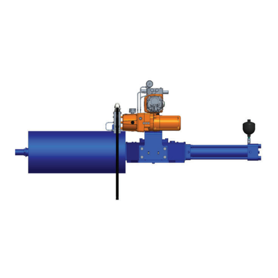
Biffi EHO (Electro-Hydraulic Operated)
Spring-Return Actuator
Copyright © Biffi. The information in this document is subject to change without notice. Updated data sheets can be obtained from our website www.biffi.it or from your nearest Biffi Center:
Biffi Italia s.r.l. - Strada Biffi 165, 29017 Fiorenzuola d'Arda (PC) – Italy PH: +39 0523 944 411 – biffi_italia@biffi.it
Installation, Operation and Maintenance Manual
VCIOM-15345-EN Rev. 1
February 2022
Advertisement
Table of Contents

Related Manuals for BIFFI EHO


Summary of Contents for BIFFI EHO
- Page 1 Spring-Return Actuator Copyright © Biffi. The information in this document is subject to change without notice. Updated data sheets can be obtained from our website www.biffi.it or from your nearest Biffi Center: Biffi Italia s.r.l. - Strada Biffi 165, 29017 Fiorenzuola d'Arda (PC) – Italy PH: +39 0523 944 411 – biffi_italia@biffi.it...
- Page 2 Revision Details Installation, Operation and Maintenance Manual February 2022 VCIOM-15345-EN Rev. 1 Revision Details Revision Date Description Prepared Checked Approved February 2022 December 2020 Document release Toscani Callegari Orefici Revision Details...
-
Page 3: Table Of Contents
Valve Preparation ..................6 Actuator Preparation ..................6 Lifting the Biffi EHO Actuator ................ 7 Installing the Biffi EHO Actuator on the Valve ..........10 Setting the Stroke Limit Stops ..............11 Hydraulic Fluid .................... 12 Accumulator (Optional) ................13 Section 3: Electrical Connections Remove Separate Terminal Chamber (STC) Cover ........ - Page 4 Actuator Operation Channels ..............42 Section 7: Local Display Module (LDM) Positions and Functions of Selector Knob ............ 44 Section 8: Customizing Biffi EHO Settings Entering the Setup Menu ................45 Change Settings ..................47 Find Setting Feature ..................50 EHO Configuration Menu ................
-
Page 5: Section 1: Introduction
The Biffi EHO accepts a wide range of single-phase, three-phase or DC power sources. A hydraulic handpump can be used to stroke the actuator during commissioning or in the event of an emergency power loss. - Page 6 February 2022 VCIOM-15345-EN Rev. 1 1.2.2 Product Attribute • Easy installation – Biffi™ EHO actuator is a totally self-contained system and designed for compactness and adaptable to new or existing valves • Biffi OLGA-H/OLGAS-H hydraulic double-acting or spring-return fail-safe actuator •...
-
Page 7: Safety Information
Identifies precautions the user must take to avoid personal injury or equipment damage. NOTICE Highlights information critical to the user’s understanding of the Biffi EHO valve actuator installation or operation. Refer to Biffi OLGA-H, OLGAS-H for Hydraulic RPHD, and RPHS Installation, Operation and Maintenance Manual for additional details. -
Page 8: Abbreviation Definitions
Section 1: Introduction Installation, Operation and Maintenance Manual February 2022 VCIOM-15345-EN Rev. 1 Abbreviation Definitions Abbreviations used in this manual and their definitions are listed in Table 1. Table 1. Abbreviation Definitions Abbreviation Definition Installation Operation Manual Emergency Shutdown Fail-Safe Single-Acting Double-Acting MAWP... -
Page 9: Section 2: Installation
Hand Tools: complete complement of open end (SAE and metric) wrenches, screwdrivers Philips and flat blade and a set of hex wrenches Chains and lifting straps that are inspected and certified for the weight of the Biffi EHO Actuator (check shipping weights) -
Page 10: Valve Preparation
90° to the run of the valve. 2.2.4 The Biffi EHO Actuator may be mounted to the valve at any time regardless of whether or not the valve is under pressure. -
Page 11: Lifting The Biffi Eho Actuator
NOTICE All Biffi EHO OLGA-H/OLGAS-H-Series or RPHD/RPHS-Series Considerations When handling any Biffi EHO OLGA-H/OLGAS-H-Series or RPHD/RPHS-Series be aware of tubing, accessories, handpump, accumulators, local display module and control enclosures. Straps and chains can become entangled and cause damage to these components. - Page 12 Section 2: Installation Installation, Operation and Maintenance Manual February 2022 VCIOM-15345-EN Rev. 1 2.4.1 OLGA-H/OLGAS-H-Series Actuators 2.4.1.1 Horizontal Pipeline Vertical Stem The OLGA-H/OLGAS-H series actuators mounting on a horizontal pipeline with a vertical valve stem should be supported using the 3 lifting point (two on the scotch yoke mechanism and one on the spring container).
- Page 13 Installation, Operation and Maintenance Manual Section 2: Installation VCIOM-15345-EN Rev. 1 February 2022 2.4.2 RPHD/RPHS-Series Actuators 2.4.2.1 Horizontal Pipeline Vertical Stem The RPHD/RPHS series actuators mounting on a horizontal pipeline with a vertical valve stem should be supported using the 4 lifting point (two on the cylinder and two on the spring container).
-
Page 14: Installing The Biffi Eho Actuator On The Valve
Installation, Operation and Maintenance Manual February 2022 VCIOM-15345-EN Rev. 1 Installing the Biffi EHO Actuator on the Valve The actuator will be bolt-mounted directly to a bracket or adaptor that will be bolted securely to the mounting flange top works of the valve. -
Page 15: Setting The Stroke Limit Stops
VCIOM-15345-EN Rev. 1 February 2022 Setting the Stroke Limit Stops 2.6.1 The Biffi OLGA-H/OLGAS-H and RPHD/RPHS Actuator is provided with bidirectional travel stops allowing 80° to 100° total travel (+/- 5° adjustment at each end of the 90° stroke). 2.6.2 Actuators are shipped from the factory with the travel stops adjusted for approximately 90°... -
Page 16: Hydraulic Fluid
Should fluid need to be added or replaced, use only factory approved hydraulic fluid. This specification covers hydraulic fluids which are approved by engineering for use in Biffi Electro-Hydraulic Operated actuator in a temperature range from -40 °C to 60 °C (-40 °F to 140 °F). 2.7.1 Approved Fluids Standard Fluid [use with -29 °C to 60 °C (-20 °F to 140 °F) applications]... -
Page 17: Accumulator (Optional)
2.8.1 Introduction The Biffi EHO Actuator may be equipped with an accumulator for modulating valve control or to enable manual operation of the actuator if there is a loss of electrical power. Accumulators always have the nitrogen pressure drained for shipping. - Page 18 Section 2: Installation Installation, Operation and Maintenance Manual February 2022 VCIOM-15345-EN Rev. 1 NOTICE For temperatures, which do not appear on the graph, the formula to calculate the pre-charge pressure shown on the General Arrangement Picture Assembly should be used. NOTICE Recheck the pre-charge pressure after a time interval sufficient to insure the nitrogen pressure is equal to the ambient temperature (a minimum of 4 hours).
- Page 19 Installation, Operation and Maintenance Manual Section 2: Installation VCIOM-15345-EN Rev. 1 February 2022 Figure 3 Typical EHO Optional Accumulator System TO MANIFOLD POWER PORT TO CYLINDER Table 3. Typical EHO Optional Accumulator System Part Number Part Name Reservoir Accumulator Nitrogen Relief Valve...
- Page 20 Section 2: Installation Installation, Operation and Maintenance Manual February 2022 VCIOM-15345-EN Rev. 1 2.8.3 Pre-charge Verification Check the nitrogen pre-charge in the accumulator periodically to ensure the accumulator is at full potential. Follow the steps below and record final readings for reference. Shut off the hydraulic power supply to the accumulator.
- Page 21 Installation, Operation and Maintenance Manual Section 2: Installation VCIOM-15345-EN Rev. 1 February 2022 2.8.5 Nitrogen Pre-charge Maintenance Record Serial Number: Tag Number: Initial GA Chart Final Nitrogen Date Signed Pre-charge Requirement Pre-charge Leak Test Installation...
-
Page 22: Section 3: Electrical Connections
Section 3: Electrical Connections Installation, Operation and Maintenance Manual February 2022 VCIOM-15345-EN Rev. 1 Section 3: Electrical Connections Remove Separate Terminal Chamber (STC) Cover WARNING Always verify electrical power is disconnected before removing the STC cover. 3.1.1 Remove cover with a strap wrench, drift, or pinch bar by rotating the cover counterclockwise. -
Page 23: Sealing Cable/Conduit Entries
All unused conduit entries must be sealed with threaded metal plugs. Recommended Terminal Connections The Biffi Electro-Hydraulic actuator terminal block connectors are wire binding screw connectors with rising captive plates. Connections can be made one of three ways: •... -
Page 24: Separate Terminal Chamber (Stc) Connections
Section 3: Electrical Connections Installation, Operation and Maintenance Manual February 2022 VCIOM-15345-EN Rev. 1 Separate Terminal Chamber (STC) Connections 3.4.1 Connect the main power supply cables, including an Earth/Ground (refer to the job specific Wiring Diagram). 3.4.2 Use the barrier strip clamp screws to connect the control wiring (refer to the job specific Wiring Diagram). -
Page 25: Discrete Controlled Inputs Connection
Installation, Operation and Maintenance Manual Section 3: Electrical Connections VCIOM-15345-EN Rev. 1 February 2022 Discrete Controlled Inputs Connection The actuator can be controlled by discrete inputs: two-wire control, three-wire control, four-wire valve control. Connect the power for these discrete inputs as detailed in Figure 9. - Page 26 Section 3: Electrical Connections Installation, Operation and Maintenance Manual February 2022 VCIOM-15345-EN Rev. 1 Table 4. Terminal Assignment Based on Network Interface Type Network Interface Type Terminal Number Signal Description Channel A + Shield Channel A - MODBUS Shield Channel B + Channel B - Output + Output -...
-
Page 27: Section 4: Set-Up/Start-Up Procedure
Information in (( )) is descriptive. When the Biffi EHO is delivered to the job site, it has been both pressure and function tested. The oil reservoir was filled to operation level when it shipped from factory. -
Page 28: Initial Check Of The Unit
Section 4: Start-up Procedure Installation, Operation and Maintenance Manual February 2022 VCIOM-15345-EN Rev. 1 Initial Check of the Unit 4.2.1 Check to ensure all hydraulic tube fittings are tight. Vibration during shipment may have loosened connections. 4.2.2 Visually inspect the unit to make sure tubing, hand valves, gauges and other equipment have not been damaged. -
Page 29: Hydraulic Test
Installation, Operation and Maintenance Manual Section 4: Start-up Procedure VCIOM-15345-EN Rev. 1 February 2022 4.4.3 Use the handle supplied with the pump to raise the pump clevis. This will draw hydraulic fluid from the reservoir (4) into the handpump. 4.4.4 Pull the pump handle down to discharge the hydraulic fluid into the cylinder of the actuator (1). -
Page 30: Check Rotation
4.6.6 If needed, correct motor rotation. NOTICE If the Biffi EHO Actuator is supplied with optional ESD, before operating a motor-powered stroke, a customer supplied ESD signal must be present and Solenoid Valve (17) energized. Start-up Procedure... -
Page 31: Self-Calibration
Self-Calibration NOTICE Self-calibration must be performed once the Biffi EHO is mounted to the valve or if the stop bolts have been adjusted on the actuator. Self-Calibration establishes the position range of the Biffi EHO. The EHO has the ability to automatically find its precise full open and full close set points after adjustments to the mechanical stops is completed. -
Page 32: Limit Switch Adjustment (Optional)
After the activity, remember to refill the product. If limit switches are supplied with the Biffi EHO, the limit switches will be factory set. The purpose of the limit switches are for position feedback and further adjustment of the limit switches are typically not required. - Page 33 Limit Switch #1 Target Illustration shows 4 Limit Switches. The Biffi EHO Illustration shows 4 Limit Switches. The SMART EHO has options for 2 or 4 Limit Switches. has options for 2 or 4 Limit Switches. NOTICE The Switch Targets will be labeled to identify the switch they operate.
- Page 34 Section 4: Start-up Procedure Installation, Operation and Maintenance Manual February 2022 VCIOM-15345-EN Rev. 1 4.8.3.4 Push down on the Target for CLOSE LS-2 and move clockwise until it is off of the switch in the clockwise direction. Refer to the wiring diagram for terminal connections for limit switch confirmation and continuity check.
-
Page 35: Function Test With Local Controls
VCIOM-15345-EN Rev. 1 February 2022 Function Test with Local Controls NOTICE If the Biffi EHO Actuator is supplied with optional ESD before operating a motor powered stroke, a customer supplied ESD signal must be present and Solenoid Valve (17) energized. 4.9.1 Ensure the Handpump Isolation Valve (8) is open and check to see Manual Bypass Valve (Lockable) is closed. -
Page 36: Other Options
Selector Switch to CLOSE and OPEN Positions to ensure control returned to the LOCAL Control Mode. 4.9.15 The functional test of the Electro Hydraulic Actuator is now complete. The Biffi EHO Actuator is now operational and ready for service. 4.10 Other Options Other options such as Solar Panels and Battery Packs may have been supplied with this order. -
Page 37: Section 5: Communication Protocols
Installation, Operation and Maintenance Manual Section 5: Communication Protocols VCIOM-15345-EN Rev. 1 February 2022 Section 5: Communication Protocols Digital control networks can interface with several different network protocols through the use of a Communication Adaptor Module (CAM), and currently, Modbus, FOUNDATION™ Fieldbus, and HART protocols are supported. - Page 38 Section 5: Communication Protocols Installation, Operation and Maintenance Manual February 2022 VCIOM-15345-EN Rev. 1 5.1.2 Multi-drop Bus Topology — Only one data path to each device from network master — No short-circuit or ground fault protection in network — Open-circuit protection only to the first cable fault —...
-
Page 39: Hart
February 2022 HART The EHO actuators are capable of offering HART7 communication protocol over the widely used 4 - 20 mA analog channels. The HART CAM interface board certified by the Fieldcom group (previously HART Communication Foundation or HCF) is capable of offering Point-to-Point, Multi-drop and Wireless HART communication topologies. -
Page 40: Foundation™ Fieldbus
VCIOM-15345-EN Rev. 1 FOUNDATION™ Fieldbus EHO actuators supporting FOUNDATION™ Fieldbus H1 protocol are fully certified by the Fieldbus Foundation and provide direct connection to the fieldbus with guaranteed interoperability with other certified devices. Each network can comprise up to 32 devices, with power for devices being provided via network cabling (assuming intrinsically safe devices are not connected to the same network). -
Page 41: Section 6: Operation
Section 6: Operation After initial start-up and commissioning procedures have been accomplished, the Biffi EHO Actuator provides a simple self-contained means of operation for a quarter-turn valve. In case of a power failure, the actuator can be operated by the use of the supplied handpump. - Page 42 Section 6: Operation Installation, Operation and Maintenance Manual February 2022 VCIOM-15345-EN Rev. 1 — (8) Handpump isolation valve: The handpump isolation valve is used to isolate the solenoid valves when using handpump to OPEN/CLOSE the actuator. — (9) Check valve. —...
- Page 43 Installation, Operation and Maintenance Manual Section 6: Operation VCIOM-15345-EN Rev. 1 February 2022 Figure 17 Electric Single-Way with Emergency Shutdown LEGEND: P - Power C - Cylinder R - Return G - Gauge Operation...
-
Page 44: Functional Description
Spring-Return Module, through speed control (7), through normally open ESD 2-way valve (17) and return to the reservoir (4). Electric Fail-Safe ((Optional)) 6.4.4 The Biffi EHO Control can be configured to stroke the actuator to Fail-Safe Position upon loss of electrical power. Operation... - Page 45 Installation, Operation and Maintenance Manual Section 6: Operation VCIOM-15345-EN Rev. 1 February 2022 6.4.5 Power Stroke of Accumulator Based Actuator (OPEN/CLOSE/Modulation) (Optional) During a normal power cycle, the motor drives the hydraulic pump. Hydraulic fluid from the pump is forced into the Accumulator and pressurizes the accumulator. Hydraulic Power Cylinder moves the actuator to the OPEN/CLOSE position which compresses the spring in the Spring-Return Module.
-
Page 46: Actuator Operation Channels
Section 6: Operation Installation, Operation and Maintenance Manual February 2022 VCIOM-15345-EN Rev. 1 Actuator Operation Channels 6.5.1 Two-Wire Control with Maintained Contact to Open or Close Two-wire control mode uses only one contact to control the actuator, with that contact often being controlled by a relay. -
Page 47: Section 7: Local Display Module (Ldm)
Installation, Operation and Maintenance Manual Section 7: Local Display Module VCIOM-15345-EN Rev. 1 February 2022 Section 7: Local Display Module (LDM) The Local Display Module consists of the following, as shown in Figure 18: • Two Small Pilot Lights: Close(CL), Open(OP) •... -
Page 48: Positions And Functions Of Selector Knob
Section 7: Local Display Module Installation, Operation and Maintenance Manual February 2022 VCIOM-15345-EN Rev. 1 Positions and Functions of Selector Knob Table 9. Selector Knob Selector Knob Rotate Control Mode Function OFF (Stop) Return position Stop movement: Prevents motor operation REMOTE (Auto) Clockwise Remote control: Allows control from remote location... -
Page 49: Section 8: Customizing Biffi Eho Settings
Installation, Operation and Maintenance Manual Section 8: Customizing Biffi EHO VCIOM-15345-EN Rev. 1 February 2022 Section 8: Customizing Biffi EHO Settings The SETUP mode must be entered to modify any configuration settings. Entering the Setup Menu 8.1.1 Place the BACK/STOP/NEXT Selector Switch to the STOP position. - Page 50 The direction of the arrows show which way to turn the knob. Do not hold the knob in any one position longer than 0.5 s or the Biffi EHO will not recognize you are trying to enter the Setup Mode.
-
Page 51: Change Settings
[C][H] displays on the Menu Key. [C][H] is the Change Settings Menu Key. Toggle the NO/YES Selector Knob to YES to enter Change Settings. Before settings can be viewed or changed, a Passcode is requested by the Biffi EHO. 8.2.3 The Passcode’s Menu Key is [P][C]. - Page 52 8.2.3.5 Repeat steps in Section 8.2.3.3 and 8.2.3.4 until all four Passcode numbers and/or letters have been entered. 8.2.3.6 Once the correct Passcode has been entered, Change Settings can be accessed and the Biffi EHO’s settings can now be viewed and changed. Customizing Biffi EHO...
- Page 53 February 2022 NOTICE If an incorrect Passcode has been entered, the Biffi EHO Menu will return to the [C][H] Menu item and the Passcode will have to be attempted again. Repeat the steps in Section 8.2.2. to 8.2.3.6 to reattempt entering the correct passcode.
-
Page 54: Find Setting Feature
Once Setup Mode has been exited, the Biffi EHO display will return to the normal display mode. Find Setting Feature The Biffi EHO comes with a find feature to quickly find a setting by entering a Menu Key. This will avoid having to navigate through the entire EHO Configuration Menu before finding a setting. - Page 55 Installation, Operation and Maintenance Manual Section 8: Customizing Biffi EHO VCIOM-15345-EN Rev. 1 February 2022 Figure 29 Change Settings (11) 8.3.5 Toggle the NO/YES Selector Knob to NO until the left the LCD display displays the number or letter corresponding to the desired Menu Key. Toggle the NO/YES Selector Knob to YES once the number or letter for the Menu Key is found.
- Page 56 After the setting has been entered, the Passcode must be entered. See instructions in Section 8.2.3.1 to 8.2.3.6 for instructions on how to enter the Passcode. 8.3.10 Once the Passcode has been accepted, the Biffi EHO will navigate directly to the entered Menu Key.
-
Page 57: Eho Configuration Menu
Menu Configuration/ Default Menu Name Calibration Value Action SETUP Enter Setup to set parameters of the Biffi EHO. Yes/No See Section 8.1 for instructions to get into the EHO Configuration Menu. FIND Biffi EHO parameter quick search feature. Yes/No See Section 8.1 for instructions on how to use the Biffi EHO quick search feature. - Page 58 If the OPEN/CLOSE selector knob is released, the actuator will stop the travel. REMOTE CONTROL Set the Biffi EHO's remote controls to momentary or maintained. Only applicable to discrete signals. A discrete remote input 0 = Momentary...
- Page 59 Menu Name Calibration Value Action LIMIT SWITCH TRIGGER POINT B Set the Biffi EHO's limit switch range. The limit switch will be triggered between 100(%) - 0(%) the limit switch trigger setpoint and 100%. The values 0 and 100 would...
- Page 60 Section 8: Customizing Biffi EHO Installation, Operation and Maintenance Manual February 2022 VCIOM-15345-EN Rev. 1 Menu Configuration/ Default Menu Name Calibration Value Action FREQUENCY CONFIGURATION 0 = DC The power supply frequency configuration. 1 = 50 Hz Feedback Only 2 = 60 Hz Note: This will be factory set.
- Page 61 Installation, Operation and Maintenance Manual Section 8: Customizing Biffi EHO VCIOM-15345-EN Rev. 1 February 2022 Table 16. Configuration Table (4) Menu Configuration/ Default Menu Name Calibration Value Action 0 = Limit Switch Open (LSO) 1 = Limit Switch Close (LSC)
- Page 62 Section 8: Customizing Biffi EHO Installation, Operation and Maintenance Manual February 2022 VCIOM-15345-EN Rev. 1 Table 18. Configuration Table (6) Menu Configuration/ Default Menu Name Calibration Value Action RELAY2 SETTING Configure Relay2 to provide either 0 = Continuous a continuous or flashing signal if...
- Page 63 1 - 253 address must be assigned for each Biffi EHO in a multi-actuator network. BAUD RATE Set the baud rate for the Biffi EHO. 0 = 4800 Note: Baud rate can be changed for 1 = 9600 Modbus network adapters only for...
- Page 64 Calibration Value Action SELF-CALIBRATION Self-Calibration establishes the position range of the Biffi EHO actuator. The Biffi EHO has the Yes / No ability to automatically find its precise full open and full close set points after adjustments to the mechanical stops are completed.
- Page 65 Only 2 = Close to Limit ESD from Host is enabled. SOFTWARE ESD OVERRIDE LOCAL MODE Configure the Biffi EHO to allow the host to override LOCAL mode control with a software 0 = NO ESD command. 1 = YES...
- Page 66 If the current value input through the Calibration analog input channel is out of the valid Status. Not range then the device calibration will fail Searchable/ and the Biffi EHO will maintain the Configurable previous calibrated value. Customizing Biffi EHO...
- Page 67 CALIBRATION FAILED (CALIBRATION STATUS) Analog Input Calibration If the input value is invalid, the device will Status. Not Searchable/ return fail. The Biffi EHO will maintain the Configurable previous calibrated value. ANALOG OUTPUT 1 CALIBRATION Yes/No Calibrate Analog Output 1 Channel.
- Page 68 The Analog Output 1 channel is calibrated Searchable/Configurable for the desired output. CALIBRATED FAILED (CALIBRATION STATUS) Analog Output 2 Calibration for Analog Output 2 channel Calibration Status. Not has failed. The Biffi EHO will maintain the Searchable/Configurable previous calibrated value. Customizing Biffi EHO...
- Page 69 1 (%) to 30 (%) 30 (%) stroke the valve during the partial stroke test. PST PAUSE TIME Configure the time the EHO will pause at the position at the of the partial stroke test 1 (s) to 30 (s) 5 (s) before returning to the position prior to initiating the partial stroke test.
- Page 70 Section 8: Customizing Biffi EHO Installation, Operation and Maintenance Manual February 2022 VCIOM-15345-EN Rev. 1 Table 26. Configuration Table (14) Menu Configuration/ Default Menu Name Calibration Value Action FACTORY SETTINGS Yes/No 1) Control Mode 2) LED Color 3) Remote Control Signal 4) Local Control Signal 6) Relay 1 –...
-
Page 71: Alarms
Alarm will activate when Biffi EHO fails to move upon command. Stay Put If log jam is enabled, the Biffi EHO will initiate log jam sequence. If log jam sequence is unsuccessful in moving the valve, the Valve Stall Alarm will activate. - Page 72 Alarm will activate when a movement command is given to the Stay Put Biffi EHO and the pressure and position of the Biffi EHO does not change as expected within ten seconds.The alarm will also activate when the motor does not operate as expected.
- Page 73 This alarm will be generated if the power supply voltage falls below the limit. Alarm Reports Only Note: This alarm is applicable for only Biffi EHOs powered by 24 V DC. HYDRAULIC LEAK ALARM This alarm is generated if the number of Drift Alarms exceed the limit Alarm Reports Only within one hour.
-
Page 74: Section 9: Troubleshooting
3. Ensure the closing and ESD speed control valves are open. Should any issue be experienced besides the symptoms noted above, please consult factory. Important check points for automatic operation of the Biffi EHO: Ensure oil level is at the proper level. -
Page 75: Hazardous Area Classification And Sil Certification
This product is only intended for use in large-scale fixed installations excluded from the scope of Directive 2011/65/EU on the restriction of the use of certain hazardous substances in electrical and electronic equipment (RoHS 2). — SIL II or SIL III Certifications(depending on Biffi EHO configuration). Hazardous Area... -
Page 76: Section 11: General Wiring Diagram
Section 11: General Wiring Diagram Installation, Operation and Maintenance Manual February 2022 VCIOM-15345-EN Rev. 1 Section 11: General Wiring Diagram 11.1 Sample Wiring Diagram Figure 32 Notes: 1. All digital inputs have an input voltage range of 18-100 V DC or 20-240 V AC. 2. - Page 77 Installation, Operation and Maintenance Manual Section 11: General Wiring Diagram VCIOM-15345-EN Rev. 1 February 2022 Table 32. Terminal Assignment Based on Network Interface Type Network Interface Type Terminal Number Signal Description Channel A + Shield Channel A - MODBUS Shield Channel B + Channel B - Output +...
-
Page 78: Applicable Operating Diagram
Section 11: General Wiring Diagram Installation, Operation and Maintenance Manual February 2022 VCIOM-15345-EN Rev. 1 11.2 Applicable Operating Diagram Here below is a preliminary list of schematics that are representing the principle of functioning. Figure 33 General Wiring Diagram... - Page 79 Installation, Operation and Maintenance Manual Section 11: General Wiring Diagram VCIOM-15345-EN Rev. 1 February 2022 Figure 34 General Wiring Diagram...
- Page 80 Section 11: General Wiring Diagram Installation, Operation and Maintenance Manual February 2022 VCIOM-15345-EN Rev. 1 Figure 35 General Wiring Diagram...
- Page 81 Installation, Operation and Maintenance Manual Section 11: General Wiring Diagram VCIOM-15345-EN Rev. 1 February 2022 Figure 36 General Wiring Diagram...
- Page 82 Section 11: General Wiring Diagram Installation, Operation and Maintenance Manual February 2022 VCIOM-15345-EN Rev. 1 Figure 37 General Wiring Diagram...
- Page 83 Installation, Operation and Maintenance Manual Section 11: General Wiring Diagram VCIOM-15345-EN Rev. 1 February 2022 Figure 38 General Wiring Diagram...
- Page 84 Section 11: General Wiring Diagram Installation, Operation and Maintenance Manual February 2022 VCIOM-15345-EN Rev. 1 Figure 39 General Wiring Diagram...
- Page 85 Installation, Operation and Maintenance Manual Section 11: General Wiring Diagram VCIOM-15345-EN Rev. 1 February 2022 Figure 40 General Wiring Diagram...
- Page 86 Section 11: General Wiring Diagram Installation, Operation and Maintenance Manual February 2022 VCIOM-15345-EN Rev. 1 Figure 41 General Wiring Diagram...
- Page 87 Installation, Operation and Maintenance Manual Section 11: General Wiring Diagram VCIOM-15345-EN Rev. 1 February 2022 Figure 42 General Wiring Diagram...
- Page 88 Section 11: General Wiring Diagram Installation, Operation and Maintenance Manual February 2022 VCIOM-15345-EN Rev. 1 Figure 43 General Wiring Diagram...
- Page 89 Installation, Operation and Maintenance Manual Section 11: General Wiring Diagram VCIOM-15345-EN Rev. 1 February 2022 Figure 44 General Wiring Diagram...
-
Page 90: Section 12: Maintenance
12.2 Service Interval Routine maintenance is generally unnecessary. Normally recommended service interval for Biffi actuators is five years or maximum actuator seal life cycle, whichever occurs first. NOTICE Storage time is considered as part of the Service Interval time. It is recommended that Service Kits be ordered approximately three (3) months prior to scheduled maintenance to assure availability. -
Page 91: Lubrication Requirements
Biffi Product Engineering: • All temperature services -40 °C to 60 °C (-40 °F to 140 °F) use Biffi™ ESL-5 lubricant. ESL-5 lubricant is contained in the Biffi Module Service Kit in tubes and the tube is marked ESL-4, 5 and 10 lubricant. - Page 92 VCIOM-15345-EN ©2022 Biffi. All rights reserved. Biffi Italia s.r.l. Strada Biffi 165 The contents of this publication are presented for information purposes only, 29017 Fiorenzuola d’Arda (PC) and while every effort has been made to ensure their accuracy, they are not...
Need help?
Do you have a question about the EHO and is the answer not in the manual?
Questions and answers