Table of Contents
Advertisement
Quick Links
4
20/04/18
3
18/04/16
2
31/07/12
1
17/11/10
0
05/05/99
Rev.
Date
OLGA – Double acting hydraulic actuator
Use and maintenance manual
DOUBLE ACTING
HYDRAULIC ACTUATOR
Use and maintenance manual
Revised data-plate
Updated applicable
regulation (chapter 1.1.1)
General update
General update
Document release
Description
© Copyright by BIFFI Italia. All right reserved.
Contents may change without notice
OLGA
MAN 606
Ermanni
Ermanni
Ermanni
Ermanni
Lazzarini
Prepared
Orefici
Vigliano
Orefici
Vigliano
Stoto
Vigliano
Stoto
Vigliano
Aliani
Ziveri
Checked
Approved
Pag. 1
Advertisement
Table of Contents

Related Manuals for BIFFI OLGA


Summary of Contents for BIFFI OLGA
- Page 1 (chapter 1.1.1) Ermanni Stoto Vigliano 31/07/12 General update Ermanni Stoto Vigliano 17/11/10 General update Lazzarini Aliani Ziveri 05/05/99 Document release Rev. Date Description Prepared Checked Approved © Copyright by BIFFI Italia. All right reserved. Pag. 1 Contents may change without notice...
-
Page 2: Table Of Contents
7 Layouts ................38 7.1 SPARE PARTS ORDER ............38 7.2 PARTS-LIST for maintenance and replacing procedure ... 39 8 Date report for maintenance operations ......47 © Copyright by BIFFI Italia. All right reserved. Pag. 2 Contents may change without notice... - Page 3 The information contained is of exclusive reserved ownership of BIFFI Italia S.r.l and may be modified without prior notice. All rights reserved. © Copyright by BIFFI Italia. All right reserved.
-
Page 4: General Warnings
2014/34/EU: Directive and safety instructions for use in hazardous area 1.1.2 Terms and conditions Biffi Italia srl guarantees that all the items produced are free of defects in workmanship and manufacturing materials and meet relevant current specifications, provided they are installed, used and serviced according to the instructions contained in the present manual. -
Page 5: Identification Plate
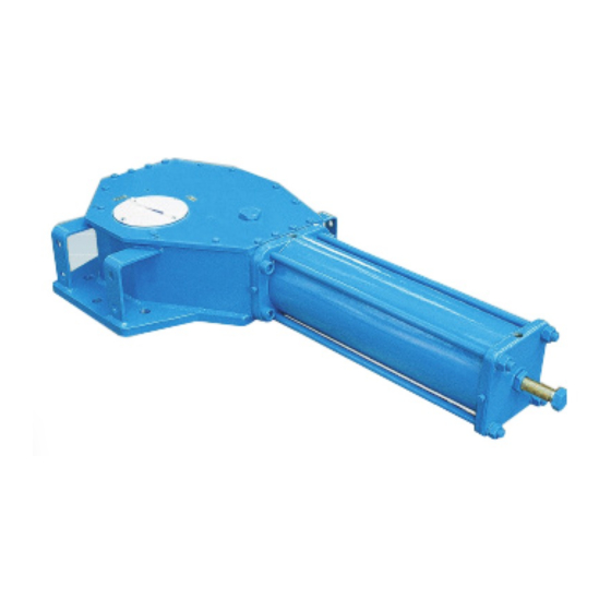
The hydraulic actuator series OLGA was engineered and is manufactured to provide maximum torque output with minimum supply pressure. The OLGA actuators is suitable for any quarter turn application such as ball, plug, butterfly valves or dampers, in both On-Off and Modulating heavy duty service. -
Page 6: Data Sheet
OLGA – Double acting hydraulic actuator Use and maintenance manual according to the shape and dimensions of the valve stem. BIFFI can supply different types of control system following Customer's requirements. The expected lifetime of actuator is approximately 25 years . -
Page 7: Actuator Handling
2.1 Figure 2.1 Example of hook with safety latch Picture 2.2 – Lifting points for OLGA / OLGA-MHP / OLGA-MSJ 1-2=Lifting points ( obligatory ) 3=Balancing point © Copyright by BIFFI Italia. All right reserved. Pag. 7... - Page 8 (MAX < 20°). • During handling, do not transport the suspended actuator above staff members in charge of the operation. © Copyright by BIFFI Italia. All right reserved. Pag. 8 Contents may change without notice...
- Page 9 OLGA – Double acting hydraulic actuator Use and maintenance manual For the transport of OLGA actuators with hydraulic manual hand- pump, when it was necessary put in horizontal position the tank of MHP, to avoid leakage on oil level stick, substitute these with a blind- plug during the transport (a specific warning label for transport in horizontal position is attached on the MHP body);...
-
Page 10: Storage
BIFFI standard tables SCN6200* and SCN6201*.If required, for the standard models size 0.3 to 6, Biffi can supply an insert bush with un-machined bore in accordance with Biffi standard table SCN6202. On request the insert bush bore can be machined by Biffi to couple the valve stem. -
Page 11: Assembly Procedure
Insert bush turned upside down Figure 3 – Insert bush + intermediate coupling flange The BIFFI insert bush with 2 external keys at 45° allows to position the keyway for the valve every 90°. Consequently actuator can be mounted in 4 positions at 90° on top of the valve. For biggest actuator models, the bore of the yoke can be machined according to the dimensions of valve stem. - Page 12 (Sect. 3.4). Fasten threaded connections. Please refer to Table 1. ❑ Table 1: nuts tightening torque Tightening torque Threading (Nm) 1100 1400 1700 © Copyright by BIFFI Italia. All right reserved. Pag. 12 Contents may change without notice...
-
Page 13: Hydraulic Connections
94/9/CE: Directive and safety instructions for use in hazardous Area(until 19 April 2016) 2014/34/EU from 20 April 2016 Remove plastic plugs from cables entries Screw firmly the cable glands. ❑ © Copyright by BIFFI Italia. All right reserved. Pag. 13 Contents may change without notice... -
Page 14: Commissioning
Check proper operation of all the due signalling ( valve position, ❑ supply pressure etc. ) Make a complete functional test in order to verify all the operations ❑ © Copyright by BIFFI Italia. All right reserved. Pag. 14 Contents may change without notice... -
Page 15: Operation And Use
The power and control systems are supplied on specific customer demand. For all the relevant information please refer to the specific technical documentation supplied. © Copyright by BIFFI Italia. All right reserved. Pag. 15 Contents may change without notice... -
Page 16: Residual Risks
Use individual protections provided for by the laws and provisions in force. 3.3 OPERATIONS ( refer to specific document: operating diagram furnished ) 3.3.1 Local manual operation Picture 5 – OLGA with hydraulic manual hand-pump The OLGA actuators can only have hydraulic manual override for local operation. -
Page 17: Emergency Manual Operation By Mhp
OLGA – Double acting hydraulic actuator Use and maintenance manual 3.3.2 Emergency manual operation by MHP The OLGA actuators can have an emergency manual override in addition to the local and/or remote control panel which controls the oil supplied by a power pack for the “normal”... -
Page 18: Calibration Of The Angular Stroke
Remove with the specific wrench (c1) the plug (t). ❑ Insert a wrench for Allen keys (c2) in the through hole until ❑ reaching the adjustment pin (g). © Copyright by BIFFI Italia. All right reserved. Pag. 18 Contents may change without notice... - Page 19 When the adjustment is over tighten the plug (t). ❑ Figure 7 – Mechanical stop of the cylinder HYDRAULIC WRENC WRENC WRENC CYLINDER H C1 H C2 H C3 SIZE (mm) (mm) (mm) © Copyright by BIFFI Italia. All right reserved. Pag. 19 Contents may change without notice...
- Page 20 ACTUATOR MODEL WRENCH C1 WRENCH C2 (mm) (mm) (mm) (mm) Figure 8 - Mechanical stop on the housing Figure 9 - Mechanical stop on the housing © Copyright by BIFFI Italia. All right reserved. Pag. 20 Contents may change without notice...
- Page 21 MSJ) Figure 9 - Mechanical stop on the end flange of manual override ACTUATOR WRENCH WRENCH SIZE (mm) (mm) ACTUATOR WRENCH WRENCH SIZE (mm) (mm) © Copyright by BIFFI Italia. All right reserved. Pag. 21 Contents may change without notice...
-
Page 22: Calibration Of Microswitches (If Foreseen)
Check that the cover and the index show the proper position of ❑ the valve (Picture 11). Tighten the screws. ❑ Picture 9 – Micro-switches Picture 10 – Cam adjustment © Copyright by BIFFI Italia. All right reserved. Pag. 22 Contents may change without notice... - Page 23 Adjust the relative cams properly. Position indicator (index) Picture 11 – Position indicator and pin for micro-switches box © Copyright by BIFFI Italia. All right reserved. Pag. 23 Contents may change without notice...
-
Page 24: Calibration Of The Operation Time (Optional)
OPERATION TIME (OPTIONAL – IF FORESEEN) The calibration of the operation time is made by Biffi Italia S.r.L according to customer requirements and to technical data-sheet included in technical documentation. If necessary it’s possible to modify or reset the operating time through two flow regulation valves (optional) placed on inlets of hydraulic cylinder (see Picture 12 and the applicable operating diagram). - Page 25 OLGA – Double acting hydraulic actuator Use and maintenance manual For OLGA actuator with Manual Hand Pump, the operating time is adjustable through two regulation valves placed on manual hand pump body ( see chapt.7.2 table 5 :sectional drawing for hydraulic control unit...
-
Page 26: Operational Tests And Inspections
To ensure the guaranteed SIL grade, according to IEC 61508, the functionality of actuator must be checked with regular intervals of time, as described in the Safety Manual © Copyright by BIFFI Italia. All right reserved. Pag. 26 Contents may change without notice... -
Page 27: Maintenance
Installation, commissioning and maintenance and repair works should be carried out by qualified staff. PERIODIC MAINTENANCE OLGA actuators are designed to operate long-term in heavy-duty operating conditions, without maintenance needs. Periodicity and regularity of inspections is particularly influenced... -
Page 28: Check And Restore Oil Level In The Hydraulic Control Unit
MINIMUM (Picture 13: minimum level is in correspondence to the end of dipstick ) until to reach the optimal (MAXIMUM) oil level . Operate the distributor lever to “Remote” position ❑ © Copyright by BIFFI Italia. All right reserved. Pag. 28 Contents may change without notice... - Page 29 Use and maintenance manual For refill use oil of the same brand as previous, refer to related technical documentation Table 2: features of hydraulic oil suggested by BIFFI Italia S.r.l for refilling in different working condition: Standard temperature conditions (-30°C/+85°): Producer...
-
Page 30: Extraordinary Maintenance
(22) surface, so as to be able to easily restore the setting of the actuator mechanical stop, once the maintenance procedures have been completed. © Copyright by BIFFI Italia. All right reserved. Pag. 30 Contents may change without notice... - Page 31 To replace the piston seal ring (46) proceed as follows: 1) Remove the existing Teflon seal ring (46) with its O-ring from their groove. © Copyright by BIFFI Italia. All right reserved. Pag. 31 Contents may change without notice...
- Page 32 9) Lubricate with protective oil or grease the O-ring (32). 10) Assemble the cover (1) and the screws (2). Tighten the screws to the recommended torque. © Copyright by BIFFI Italia. All right reserved. Pag. 32 Contents may change without notice...
- Page 33 AFTER MAINTENANCE OPERATIONS CARRY OUT A FEW ACTUATOR OPERATIONS TO CHECK THAT ITS MOVEMENT IS REGULAR AND THAT THERE IS NO OIL LEAKAGE THROUGH THE SEALS. © Copyright by BIFFI Italia. All right reserved. Pag. 33 Contents may change without notice...
- Page 34 OLGA – Double acting hydraulic actuator Use and maintenance manual © Copyright by BIFFI Italia. All right reserved. Pag. 34 Contents may change without notice...
-
Page 35: Lubrication Of Mechanism
For this operation it is necessary to disassemble the mechanism cover. In larger actuators the lubrication can be performed through the inspection holes of the cover after removing the plugs. The following grease is used by BIFFI for standard working temperature and suggested for re-lubrication: AGIP MU/EP/2... - Page 36 (ex. metallic, and plastic materials, fluids etc.) and send them to differentiated waste collection sites, as provided for by the laws and provisions in force. © Copyright by BIFFI Italia. All right reserved. Pag. 36 Contents may change without notice...
-
Page 37: Troubleshooting
Leakages on the check Call BIFFI Italia S.r.l. valve of the hydraulic Customer Service control group © Copyright by BIFFI Italia. All right reserved. Pag. 37 Contents may change without notice... -
Page 38: Layouts
Use and maintenance manual 7 Layouts SPARE PARTS ORDER For spare parts order to the relevant BIFFI office please make reference to BIFFI order confirmation concerning all the supply, and serial number of the actuator (Sect. 1.2) for any specific spare part for a specific actuator model. -
Page 39: Parts-List For Maintenance And Replacing Procedure
OLGA – Double acting hydraulic actuator Use and maintenance manual 7.2 PARTS-LIST FOR MAINTENANCE AND REPLACING PROCEDURE Table 1: Scotch-yoke mechanism © Copyright by BIFFI Italia. All right reserved. Pag. 39 Contents may change without notice... - Page 40 OLGA – Double acting hydraulic actuator Use and maintenance manual Table 2: Hydraulic cylinder © Copyright by BIFFI Italia. All right reserved. Pag. 40 Contents may change without notice...
- Page 41 OLGA – Double acting hydraulic actuator Use and maintenance manual Table 3: hydraulic cylinder for MHP (optional) © Copyright by BIFFI Italia. All right reserved. Pag. 41 Contents may change without notice...
- Page 42 OLGA – Double acting hydraulic actuator Use and maintenance manual Table 4: assembly kit © Copyright by BIFFI Italia. All right reserved. Pag. 42 Contents may change without notice...
- Page 43 OLGA – Double acting hydraulic actuator Use and maintenance manual Table 5: Hydraulic control unit MHP © Copyright by BIFFI Italia. All right reserved. Pag. 43 Contents may change without notice...
- Page 44 OLGA – Double acting hydraulic actuator Use and maintenance manual © Copyright by BIFFI Italia. All right reserved. Pag. 44 Contents may change without notice...
- Page 45 OLGA – Double acting hydraulic actuator Use and maintenance manual © Copyright by BIFFI Italia. All right reserved. Pag. 45 Contents may change without notice...
- Page 46 OLGA – Double acting hydraulic actuator Use and maintenance manual Table 6: Jackscrew manual override MSJ © Copyright by BIFFI Italia. All right reserved. Pag. 46 Contents may change without notice...
-
Page 47: Date Report For Maintenance Operations
Next maintenance operation date: ……… exec. by : ………… ……… exec. by : ………… Start-up date : ( in factory, on delivery ).……………………. .……………………. ( on plant ) © Copyright by BIFFI Italia. All right reserved. Pag. 47 Contents may change without notice...
Need help?
Do you have a question about the OLGA and is the answer not in the manual?
Questions and answers