Table of Contents
Advertisement
Quick Links
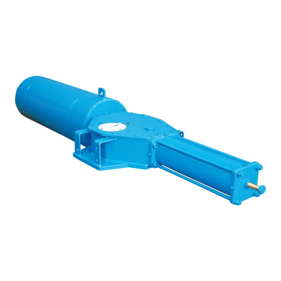
Biffi OLGAS
Spring-Return Hydraulic Actuators
Copyright © Biffi. The information in this document is subject to change without notice. Updated data sheets can be obtained from our website www.biffi.it or from your nearest Biffi Center:
Biffi Italia s.r.l. - Strada Biffi 165, 29017 Fiorenzuola d'Arda (PC) – Italy PH: +39 0523 944 411 – biffi_italia@biffi.it
Installation, Operation and Maintenance Manual
MAN 608 Rev. 5
December 2020
Advertisement
Table of Contents

Related Manuals for BIFFI OLGAS


Summary of Contents for BIFFI OLGAS
- Page 1 Spring-Return Hydraulic Actuators Copyright © Biffi. The information in this document is subject to change without notice. Updated data sheets can be obtained from our website www.biffi.it or from your nearest Biffi Center: Biffi Italia s.r.l. - Strada Biffi 165, 29017 Fiorenzuola d'Arda (PC) – Italy PH: +39 0523 944 411 – biffi_italia@biffi.it...
- Page 2 Revision Details Installation, Operation and Maintenance Manual December 2020 MAN 608 Rev. 5 Revision Details Revision Date Description Prepared Checked Approved December 2020 Migration to new template April 2020 Updated DATAPLATE Ermanni Orefici Vigliano April 2018 Updated applicable regulation (chapter 1.1.1) Ermanni Orefici Vigliano...
-
Page 3: Table Of Contents
Installation, Operation and Maintenance Manual Table of Contents MAN 608 Rev. 5 December 2020 Table of Contents Section 1: General Warnings Generalities ....................1 1.1.1 Applicable regulation ................. 1 1.1.2 Terms and conditions ................. 2 Identification Plate ..................2 Introducing the Actuator ................3 Data Sheet .................... - Page 4 Table of Contents Installation, Operation and Maintenance Manual December 2020 MAN 608 Rev. 5 Section 4: Operational Tests and Inspections Operational Tests and Inspections ................. 27 Section 5: Maintenance Periodic Maintenance .................. 28 5.1.1 Check and Restore Oil Level in the Hydraulic Manual Handpump ..29 Extraordinary Maintenance .................
-
Page 5: Section 1: General Warnings
Biffi Italia s.r.l. pays the highest attention to collecting and verifying the documentation contained in this user manual. However Biffi Italia S.r.l. is not liable for any mistakes con- tained in this manual, for damage or accidents due to the use of the latter. The information contained is of exclusive reserved ownership of Biffi Italia s.r.l. -
Page 6: Terms And Conditions
1.1.2 Terms and conditions Biffi Italia s.r.l. guarantees that all the items produced are free of defects in workmanship and manufacturing materials and meet relevant current specifications, provided they are installed, used and serviced according to the instructions contained in the present manual. -
Page 7: Introducing The Actuator
The actuator yoke has a hole with keyways suitable for the assembly of an insert bush the internal hole of which is machined (by Biffi or at Customer's care), according to the shape and dimensions of the valve stem. Biffi can supply different types of control system following Customer's requirements. -
Page 8: Section 2: Installation
Section 2: Installation Installation, Operation and Maintenance Manual December 2020 MAN 608 Rev. 5 Section 2: Installation Checks upon Actuator Receipt • Check that the model, the serial number of the actuator and the technical data reported on the identification plate correspond with those of order confirmation, see Section 1.2. - Page 9 Section 2: Installation MAN 608 Rev. 5 December 2020 Figure 4 Lifting points for OLGAS actuators 1 = point of support 2 = supports for lateral positioning 3 = don’t lay the actuator on tie-rods of cylinder/s 1-2 = Lifting points (obligatory) and don’t lay the actuator on accessories...
- Page 10 Figure 5 Figure 6 For the transport of OLGAS with hydraulic manual handpump, when it was necessary put in horizontal position the tank of MHP, to avoid leakage on oil level stick, substitute these with a blind-plug during the transport (a specific warning label for transport in horizontal position is attached on the MHP body);...
-
Page 11: Storage
Installation, Operation and Maintenance Manual Section 2: Installation MAN 608 Rev. 5 December 2020 OMFB manual handpump should be transported and used with MHP tank in horizontal position, but in position 3 of follow picture (extracted from OMFB technical documentation) it’s necessary change the position of suction pipe and breather cap. Figure 7 Fixing positions Invert the position of the breather cap... -
Page 12: Actuator Assembly On The Valve
NOTICE To fix the actuator to the valve flange must be used the stud bolts and nuts supplied by Biffi. In case the actuator is supplied without stud bolts and nuts the following materials must be used as a minimum: •... - Page 13 Installation, Operation and Maintenance Manual Section 2: Installation MAN 608 Rev. 5 December 2020 Figure 8 Coupling dimensions - Models 0.3 to 6 Drive sleeve +0.1 Ø d Ø d Ø d ±0.2 Ø d N. threaded holes PCD, number and size according to ISO 5211 (but the holes are on centerline instead of...
- Page 14 Section 2: Installation Installation, Operation and Maintenance Manual December 2020 MAN 608 Rev. 5 Figure 9 Coupling dimensions - Models 14 to 42 Drive sleeve Ø Ø +0.1 Ø ±0.2 Ø N. threaded holes PCD, number and size according to ISO 5211 Flow line Ø...
- Page 15 Installation, Operation and Maintenance Manual Section 2: Installation MAN 608 Rev. 5 December 2020 Figure 10 Coupling dimensions - Models 50 and 60 Drive sleeve Ø Ø +0.1 Ø ±0.2 Ø N. THREADED HOLES Flange sizing according to ISO Flow line Ø...
- Page 16 Insert bush turned upside down The Biffi insert bush with 2 external keys at 45° allows to position the keyway for the valve every 90°. Consequently actuator can be mounted in 4 positions at 90° on top of the valve.
-
Page 17: Assembly Procedure
Installation, Operation and Maintenance Manual Section 2: Installation MAN 608 Rev. 5 December 2020 2.4.2 Assembly Procedure NOTICE Failure to comply with the following procedures may impair product warranty. WARNING Installation, commissioning and maintenance, and repair works should be carried out by qualified staff. -
Page 18: Hydraulic Connections
Section 2: Installation Installation, Operation and Maintenance Manual December 2020 MAN 608 Rev. 5 Hydraulic Connections WARNING Check that the values of hydraulic supply available are compatible with those reported on the identification plate of the actuator. NOTICE The connections should be made by qualified staff. Use pipes, fittings and connections appropriate as for type, material and dimensions. -
Page 19: Commissioning
NOTICE if necessary to mount components not in Biffi scope of supply, please check the accessories mounting hole details in the documents TN 1028 ( for metric dimension) or TN 1028U (for imperial dimension). -
Page 20: Section 3: Operation And Use
Section 3: Operation and Use Installation, Operation and Maintenance Manual December 2020 MAN 608 Rev. 5 Section 3: Operation and Use Operation Description The actuator is operated by: Pressurized motor fluid. Elastic return of compression helicoidally spring. In the first case the alimentation fluid pressurizes a chamber of the cylinder and compresses the spring (Figure 4);... -
Page 21: Residual Risks
(refer to specific document: operating diagram furnished). 3.3.1 Emergency Manual Operation The OLGAS actuators can have an emergency manual override in addition to the local and/or remote control panel which controls the oil supplied by a power pack for the “normal” actuator operation. - Page 22 Section 3: Operation and Use Installation, Operation and Maintenance Manual December 2020 MAN 608 Rev. 5 Figure 14 OLGAS with hydraulic power pack Figure 15 1. Scotch yoke mechanism 2. Hydraulic cylinder 3. Spring cartridge Hydraulic connection to 4. Hydraulic manual override the hydraulic control panel 5.
-
Page 23: Remote Control Operations
Biffi has the ability to apply advanced engineering technology to the design and manufacture of hydraulic controls and accessories. The experience and the knowledge acquired in the actuator industry allow Biffi to meet with the highest requirements for control modes and operating conditions by correct selection of schematics, components, materials and protection treatment. - Page 24 December 2020 MAN 608 Rev. 5 Biffi has the ability to apply advanced engineering technology to the design and manufacture of hydraulic power packs, in order to meet with the highest requirements for operating modes and working conditions by a correct selection of schematics, components, materials and protection treatment.
-
Page 25: Calibration Of The Angular Stroke
Installation, Operation and Maintenance Manual Section 3: Operation and Use MAN 608 Rev. 5 December 2020 Calibration of the Angular Stroke The angular stroke of the yoke can be adjusted between 82°÷98° (±4° with respect to the nominal positions of complete opening and closing) by means the mechanical stops screwed at the end of spring-cartridge, and into the end flange of the pneumatic cylinder (Figure 17). - Page 26 Section 3: Operation and Use Installation, Operation and Maintenance Manual December 2020 MAN 608 Rev. 5 Figure 18 Mechanical stop of the cylinder Table 6. Hydraulic Cylinder Size Wrench C1 (mm) Wrench C2 (mm) Wrench C3 (mm) Operation and Use...
- Page 27 Installation, Operation and Maintenance Manual Section 3: Operation and Use MAN 608 Rev. 5 December 2020 For the adjustment of the travel stop screw, for cartridge model from 006 to 150, proceed as follows: Figure 19 Models from 006 to 150 For the adjustment of the travel stop screw, for cartridge model from 200 to 15600, proceed as follows: Figure 18...
- Page 28 Section 3: Operation and Use Installation, Operation and Maintenance Manual December 2020 MAN 608 Rev. 5 To operate the adjustments, refer to following Tables: Table 7. Spring container size Wrench C1 (mm) Wrench C2 (mm) 0100 0150 Table 8. Spring container size Wrench c1 (mm) Wrench c2 (mm) 0200...
-
Page 29: Calibration Of Micro-Switches (If Foreseen)
Installation, Operation and Maintenance Manual Section 3: Operation and Use MAN 608 Rev. 5 December 2020 Calibration of Micro-switches (If Foreseen) Calibration of Micro-switches (If Foreseen) WARNING Refer only to technical documentation related to installed switch-box model. NOTICE For mounting interface dimension of the Limit Switch box on the cover of the actuator, please refer to TN1163V (for metric dimension) or TN1163VU (for imperial dimension). -
Page 30: Calibration Of The Operation Time (If Required)
MAN 608 Rev. 5 Calibration of the Operation Time (If Required) The calibration of the operation time is made by Biffi Italia s.r.l, according to customer requirements and to technical data-sheet included in technical documentation. If necessary it’s possible to modify or reset the operating time through two flow regulation valves (optional) placed on inlets of hydraulic cylinder (see Figure 22 and the applicable operating diagram). -
Page 31: Section 4: Operational Tests And Inspections
Installation, Operation and Maintenance Manual Section 4: Operational Tests and Inspections MAN 608 Rev. 5 December 2020 Section 4: Operational Tests and Inspections NOTICE To ensure the guaranteed SIL grade, according to IEC 61508, the functionality of actuator must be checked with regular intervals of time, as described in the Safety Manual. Operational Tests and Inspections... -
Page 32: Section 5: Maintenance
Installation, commissioning and maintenance, and repair works should be carried out by qualified staff. Periodic Maintenance OLGAS actuators are designed to operate long-term in heavy-duty operating conditions, without maintenance needs. NOTICE Periodicity and regularity of inspections is particularly influenced by specific environmental and working conditions. -
Page 33: Check And Restore Oil Level In The Hydraulic Manual Handpump
Section 5: Maintenance Installation, Operation and Maintenance Manual MAN 608 Rev. 5 December 2020 Figure 23 Level measuring stick Maximum level Minimum level 5.1.1 Check and Restore Oil Level in the Hydraulic Manual Handpump Operate the distributor lever to “manual operation” to operate valve and to compress completely the actuator spring. - Page 34 MAN 608 Rev. 5 NOTICE For refill use oil of the same brand as previous, refer to related technical documentation. Table 10. Features of Hydraulic Oil Used by Biffi Italia s.r.l. for Refilling Different Working Condition: Standard temperature conditions (-30 °C/+85 °C): Producer...
-
Page 35: Extraordinary Maintenance
Section 5: Maintenance Installation, Operation and Maintenance Manual MAN 608 Rev. 5 December 2020 Extraordinary Maintenance If there are leaks in the hydraulic cylinder, or a malfunction in the mechanical components, or in case of scheduled preventive maintenance, the actuator must be disassembled and seals must be replaced with reference to the follow general sectional drawing and adopting the following procedures: WARNING... -
Page 36: Replacement Of Cylinder Seals
Section 5: Maintenance Installation, Operation and Maintenance Manual December 2020 MAN 608 Rev. 5 5.2.1 Replacement of Cylinder Seals Unscrew the cover of the adjustment screw (23). Measure the distance of the stop screw (20) with reference to the end flange (22) surface, so as to be able to easily restore the setting of the actuator mechanical stop, once the maintenance procedures have been completed. - Page 37 Section 5: Maintenance Installation, Operation and Maintenance Manual MAN 608 Rev. 5 December 2020 Reassemble Assemble the new gasket (44-46) after cleaning the surfaces of housing (8), the flange (22) and head flange (49) which are in contact. Assemble the head flange (49), replace the washers if damaged, tighten the screws (7) to the recommended torque.
- Page 38 Section 5: Maintenance Installation, Operation and Maintenance Manual December 2020 MAN 608 Rev. 5 Figure 26 OLGAS Spring-Return Hydraulic Actuator Table 11. Parts List Item Description Item Description Spring thrust flange Stop-setting screw Rod bushing Spring container Container rod Spring...
-
Page 39: Lubrication Of Mechanism
It’s necessary restore the grease into spring-cartridge (for this operation remove the plug on end-flange of spring-cartridge and restore a generous coating of grease). The following grease is used by Biffi for standard working temperature and suggested for re-lubrication: Table 12. -
Page 40: Dismantling And Demolition
Section 5: Maintenance Installation, Operation and Maintenance Manual December 2020 MAN 608 Rev. 5 Dismantling and Demolition Before starting the disassembly a large area should be created around the actuator so to allow any kind of movement without problems of further risks created by worksite. WARNING Before disassembling the actuator it is necessary to close the hydraulic feed line and discharge oil pressure from the cylinder of the actuator, from the control unit and from the... -
Page 41: Section 6: Troubleshooting
Lack of power supply Restore it Lack of hydraulic supply Open line interception valve Failure of the spring Call Biffi Italia s.r.l. Customer Service Actuator does not work Blocked valve Repair or replace Wrong position of the distributor of the... -
Page 42: Section 7: Layouts
Section 7: Layouts Spare Parts Order For spare parts order to the relevant Biffi office, please make reference to BiffiI order confirmation concerning all the supply, and serial number of the actuator (Section 1.2) for any specific spare part for a specific actuator model. -
Page 43: Parts List For Maintenance And Replacing Procedure
Installation, Operation and Maintenance Manual Section 7: Layouts MAN 608 Rev. 5 December 2020 Parts List for Maintenance and Replacing Procedure Figure 27 Scotch yoke mechanism Table 14. Parts List Item Description Material O-ring * NBR Yoke bushing Bronze Retainer ring Stainless steel Housing Carbon steel... - Page 44 Section 7: Layouts Installation, Operation and Maintenance Manual December 2020 MAN 608 Rev. 5 Figure 28 Hydraulic cylinder Table 15. Parts List Item Description Material Piston rod bushing Steel + bronze + TeflonWW Head flange Carbon steel O-ring * NBR rubber Piston rod seal ring * Teflon + graphite O-ring...
- Page 45 Installation, Operation and Maintenance Manual Section 7: Layouts MAN 608 Rev. 5 December 2020 Figure 29 Spring cartridge Table 16. Parts List Item Description Material Carbon steel Washer Carbon steel Sealing washer * PVC Stop-setting screw Carbon steel Spring container Carbon steel Spring Carbon steel...
- Page 46 Section 7: Layouts Installation, Operation and Maintenance Manual December 2020 MAN 608 Rev. 5 Figure 30 Assembly kit Table 17. Parts List Item Description Material Screw Teflon coated alloy steel Gasket * Fiber Plug Carbon steel Washer Carbon steel Screw Alloy steel Gasket * Fiber...
- Page 47 Installation, Operation and Maintenance Manual Section 7: Layouts MAN 608 Rev. 5 December 2020 Figure 31 Hydraulic control unit MHP Layouts...
- Page 48 Section 7: Layouts Installation, Operation and Maintenance Manual December 2020 MAN 608 Rev. 5 Table 18. Parts List Item Description Material Plate Carbon Steel Stuffing box Aluminum Seal ring Teflon + graphite Stem Stainless steel Plug Stainless steel Oil tank Carbon steel Oil tank cover Carbon steel...
- Page 49 Installation, Operation and Maintenance Manual Section 7: Layouts MAN 608 Rev. 5 December 2020 Figure 31 Hydraulic control unit - handpump Table 19. Parts List Item Description Material Ball Stainless steel Delivery valve bush Carbon steel Suction valve bush Carbon steel Spring Stainless steel Suction valve seat...
-
Page 50: Section 8: Date Report For Maintenance Operations
Section 8: Date Report for Maintenance Operations Installation, Operation and Maintenance Manual December 2020 MAN 608 Rev. 5 Section 8: Date Report for Maintenance Operations Last maintenance operation date: (in factory, on delivery): ……… exec. by: ………… ……… exec. by: ………… ………... - Page 51 Notes Installation, Operation and Maintenance Manual MAN 608 Rev. 5 December 2020 This page intentionally left blank...
- Page 52 VCIOM-03745-EN ©2020 Biffi. All rights reserved. Biffi Italia s.r.l. Strada Biffi 165 The contents of this publication are presented for information purposes only, 29017 Fiorenzuola d’Arda (PC) and while every effort has been made to ensure their accuracy, they are not...
Need help?
Do you have a question about the OLGAS and is the answer not in the manual?
Questions and answers