Table of Contents
Advertisement
Quick Links
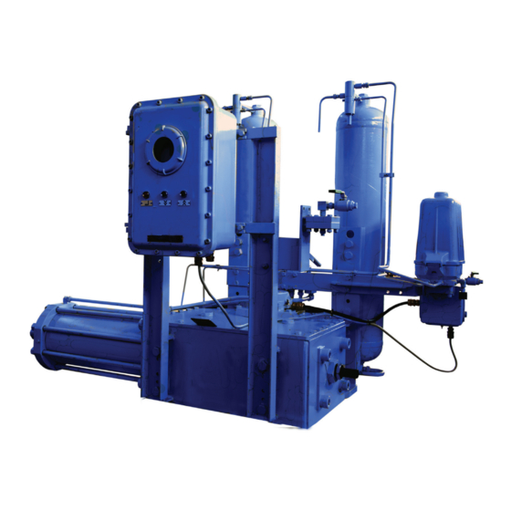
Biffi GPO-EAC
Gas-Hydraulic Actuator
Copyright © Biffi. The information in this document is subject to change without notice. Updated data sheets can be obtained from our website www.biffi.it or from your nearest Biffi Center:
Biffi Italia s.r.l. - Strada Biffi 165, 29017 Fiorenzuola d'Arda (PC) – Italy PH: +39 0523 944 411 – biffi_italia@biffi.it
Installation, Operation and Maintenance Manual
MAN 571_EAC Rev. 1
September 2020
Advertisement
Table of Contents

Related Manuals for BIFFI GPO-EAC


Summary of Contents for BIFFI GPO-EAC
- Page 1 Gas-Hydraulic Actuator Copyright © Biffi. The information in this document is subject to change without notice. Updated data sheets can be obtained from our website www.biffi.it or from your nearest Biffi Center: Biffi Italia s.r.l. - Strada Biffi 165, 29017 Fiorenzuola d'Arda (PC) – Italy PH: +39 0523 944 411 – biffi_italia@biffi.it...
- Page 2 Revision Details Installation, Operation and Maintenance Manual September 2020 MAN 571_EAC Rev. 1 Revision Details Rev. Date Description Prepared Approved September 2020 General update (migration to new template) October 2017 Document release Ermanni Orefici Revision Details...
-
Page 3: Table Of Contents
Installation, Operation and Maintenance Manual Table of Contents MAN 571_EAC Rev. 1 September 2020 Table of Contents Section 1: General Warnings Generalities ....................1 1.1.1 Applicable Regulation ................. 1 1.1.2 Terms and Conditions ................2 Identification Plate ..................2 Introducing the Actuator ................2 Data Sheet ..................... - Page 4 Table of Contents Installation, Operation and Maintenance Manual September 2020 MAN 571_EAC Rev. 1 Section 5: Maintenance Periodic Maintenance ................... 35 5.1.1 Check and Restore Oil Level in the Gas-Hydraulic Tanks ..... 36 Extraordinary Maintenance ................38 5.2.1 Lubrication of Mechanism ..............38 5.2.2 Replacing the Seals of the Cylinder ............
-
Page 5: Section 1: General Warnings
Biffi Italia s.r.l. pays the highest attention to collecting and verifying the documentation contained in this user manual. However Biffi Italia s.r.l. is not liable for any mistakes contained in this manual, for damage or accidents due to the use of the latter. The information contained is of exclusive reserved ownership of Biffi Italia s.r.l. -
Page 6: Terms And Conditions
1.1.2 Terms and Conditions Biffi Italia s.r.l. guarantees that all the items produced are free of defects in workmanship and manufacturing materials and meet relevant current specifications, provided they are installed, used and serviced according to the instructions contained in the present manual. -
Page 7: Introducing The Actuator
Installation, Operation and Maintenance Manual Section 1: General Warnings MAN 571_EAC Rev. 1 September 2020 Introducing the Actuator The gas hydraulic GPO actuator is designed and used for the operation of quarter-turn valves (ball valves and plug valves) installed on gas transportation lines, in compressor stations and everywhere a high pressure gas supply is available. -
Page 8: Section 2: Installation
Section 2: Installation Installation, Operation and Maintenance Manual September 2020 MAN 571_EAC Rev. 1 Section 2: Installation Checks Upon Actuator Receipt • Check that the model, the serial number of the actuator and the technical data reported on the identification plate correspond with those of order confirmation (Section 1.2). - Page 9 Section 2: Installation Installation, Operation and Maintenance Manual MAN 571_EAC Rev. 1 September 2020 Figure 3 Lifting Points Installation...
- Page 10 Section 2: Installation Installation, Operation and Maintenance Manual September 2020 MAN 571_EAC Rev. 1 Figure 4 Lifting Points 1, 2 = Lifting points (obligatory) 3 = Balancing point Figure 5 Lifting Points 1 = Point of support 2 = Don’t lay the actuator on tie-rods Installation...
-
Page 11: Instruction For Transport With Tanks In Horizontal Position
If the necessity of horizontal transport is known at the order date, Biffi Italia s.r.l. can provide two ball type isolation valves at the inlet of the bottles. In this case it’s very easy to isolate the oil bottles, simply closing the stop valves before the boxing. - Page 12 Section 2: Installation Installation, Operation and Maintenance Manual September 2020 MAN 571_EAC Rev. 1 Disassembly for shipping: Figure 7 • Unloose the nuts of the compression fittings R on pneumatic connections nipple S (Figure 8). Figure 8 Installation...
- Page 13 Section 2: Installation Installation, Operation and Maintenance Manual MAN 571_EAC Rev. 1 September 2020 • Remove pneumatic tubes T from connection nipple S (Figure 9). Figure 9 • Plug the connection nipple S with proper cap plugs (Figure 10). Figure 10 Cap plug Installation...
- Page 14 Section 2: Installation Installation, Operation and Maintenance Manual September 2020 MAN 571_EAC Rev. 1 • Plug the pneumatic pipe ends with plastic plugs for fittings (Figure 11). Figure 11 Plastic plug Re-assembly before “start-up” of actuator: • Remove protection plugs from compression fittings R and connections S. •...
- Page 15 Section 2: Installation Installation, Operation and Maintenance Manual MAN 571_EAC Rev. 1 September 2020 When torque limiting devices are furnished , proceeded as follow : (See Figure 12) Disassembly for shipping : • Remove tubes (T1 and T2) on connections S1, S2 by unloosing the nuts of the compression fittings R.
-
Page 16: Procedure If Oil Leaks From The Tanks Into The Pneumatic Valves
Section 2: Installation Installation, Operation and Maintenance Manual September 2020 MAN 571_EAC Rev. 1 2.2.2 Procedure to Follow If Oil Leaks from the Tanks into the Pneumatic Valves NOTICE If the actuator tanks are kept in horizontal axis by mistake, and the oil inside them enters into the pneumatic connection pipes and in the control pneumatic valves, it is necessary to wash with dry air (high flow, low pressure) the interior of valves and pipes: connect an air or a dry nitrogen supply to the threaded hole of actuator supply and disconnect the... -
Page 17: Storage
For coupling to the valve, the housing is provided with a flange with threaded holes according to Biffi standard tables (SCN6200 SCN6201). The number, dimensions and diameter of the holes are made in accordance with ISO 5211, but for actuator models 0.3 to 6 the holes are drilled on the centreline in order to allow an easier assembly of an... - Page 18 Section 2: Installation Installation, Operation and Maintenance Manual September 2020 MAN 571_EAC Rev. 1 Figure 13 Drive sleeve Ø Ø +0.1 Ø ±0.2 Ø N. THREADED HOLES PCD, holes, number and size according to ISO 5211 (but the holes are on centerline instead of straddle the centerline) Flow line °...
- Page 19 Section 2: Installation Installation, Operation and Maintenance Manual MAN 571_EAC Rev. 1 September 2020 Figure 14 Drive sleeve Ø Ø +0.1 Ø ±0.2 Ø N. THREADED HOLES PCD, holes, number and size according to ISO 5211 Flow line Ø +0.2 +0.1 Top view of the scotch yoke mechanism (actuator shown in closed position)
- Page 20 264.8 264.8 If required, for the standard models size 0.3 to 6, Biffi can supply an insert bush with un-machined bore in accordance with Biffi standard table SCN6202 enclosed (see following pages). On request the insert bush bore can be machined by Biffi to couple the valve stem.
- Page 21 Insert bush turned upside down The Biffi insert bush with 2 external keys at 45° allows to position the keyway for the valve every 90°. Consequently actuator can be mounted in 4 positions at 90° on top of the valve.
-
Page 22: Assembly Procedure
Section 2: Installation Installation, Operation and Maintenance Manual September 2020 MAN 571_EAC Rev. 1 2.4.2 Assembly Procedure NOTICE Failure to comply with the following procedures may impair product warranty. WARNING Installation, commissioning and maintenance and repair works should be carried out by qualified staff. -
Page 23: Pneumatic Connections
Section 2: Installation Installation, Operation and Maintenance Manual MAN 571_EAC Rev. 1 September 2020 Table 5. Nuts Tightening Torque Threading Tightening torque (Nm) 1100 1400 1700 The screwing values in Table 5 were calculated considering the materials ASTM A320 L7 for screws or tie rods and ASTM A194 gr.2H for the nuts. -
Page 24: Electrical Connections (If Any)
Section 2: Installation Installation, Operation and Maintenance Manual September 2020 MAN 571_EAC Rev. 1 Electrical Connections (If Any) WARNING Use components appropriate as for type, material and dimensions. The connections should be made by qualified staff. Before carrying out any operation, cut line power off. NOTICE Safety provisions: 2006/95/EC: Directive for low voltage equipment (until 19 April 2016) 2014/35/EU... -
Page 25: Commissioning
Section 2: Installation Installation, Operation and Maintenance Manual MAN 571_EAC Rev. 1 September 2020 Commissioning NOTICE Check that values of electrical supply to the control group (if foreseen) are compatible with those on the plate on the junction box (Figure 17). WARNING Installation, commissioning and maintenance and repair works should be made by qualified staff. -
Page 26: Section 3: Operation And Use
Section 3: Operation and Use Installation, Operation and Maintenance Manual September 2020 MAN 571_EAC Rev. 1 Section 3: Operation and Use Operation Description The supply gas pressurizes oil contained in the gas-hydraulic tank relevant to the operation to carry out (opening or closing) (Figure 18). Oil, (Figure 20), arrives to the manual hydraulic control group and pressurizes a chamber of the cylinder: this starts the linear motion of the piston and the consequent rotation motion of the scocth yoke, to which the valve stem is coupled. - Page 27 Installation, Operation and Maintenance Manual Section 3: Operation and Use MAN 571_EAC Rev. 1 September 2020 Figure 18 Operating Diagram Open Close Electronic connection to solenoid valves and to micro-switches exhaust Auxiliary gas supply Gas supply connection Gas supply connection (upstream the valve) (downstream the valve) Pneumatic connection...
- Page 28 When the gas supply to the actuator is not always available, a storage tank engineered and manufactured according to the applicable code and working conditions is provided. For any particular requirements it is advisable to contact Biffi sales offices, wich will provide the most suitable and convenient solutions to the various needs. (Figure 19).
-
Page 29: Residual Risks
Installation, Operation and Maintenance Manual Section 3: Operation and Use MAN 571_EAC Rev. 1 September 2020 Figure 20 Flow Regulator Valves The speed of operation can be adjusted on site by two flow control valves (see Figure 20 and Section 3.6). Residual Risks WARNING It is recommended to pipe exhaust gas. -
Page 30: Local Hydraulic Manual Operation
Section 3: Operation and Use Installation, Operation and Maintenance Manual September 2020 MAN 571_EAC Rev. 1 Figure 21 Double Solenoid Valve With Manual Control • Arrange the distributor to the “Automatic” position (Figure 22). • Operate the manual control lever of the double solenoid valve in the control group, relevant to the operation to carry out (opening or closing) (Figure 21). -
Page 31: Remote Operation
Installation, Operation and Maintenance Manual Section 3: Operation and Use MAN 571_EAC Rev. 1 September 2020 3.3.3 Remote Operation • In case of remote control, arrange the distributor to “Automatic” position (Figure 22), and from the control room send the electric signal corresponding to the operation to carry out (opening or closing). -
Page 32: Calibration Of The Angular Stroke
Section 3: Operation and Use Installation, Operation and Maintenance Manual September 2020 MAN 571_EAC Rev. 1 Calibration of the Angular Stroke The angular stroke of the yoke can be adjusted between 82°÷98° (±4° with respect to the nominal positions of complete opening and closing) by means the mechanical stops screwed into the left side of the housing (open valve) and into the end flange of the pneumatic cylinder (closing) (Figure 23). - Page 33 Installation, Operation and Maintenance Manual Section 3: Operation and Use MAN 571_EAC Rev. 1 September 2020 For the adjustment of the mechanical stop on the end flange of cylinder, follow these steps (Figure 25): • Remove with the specific wrench (c1) the plug (t). •...
-
Page 34: Calibration Of Micro-Switches (If Foreseen)
Section 3: Operation and Use Installation, Operation and Maintenance Manual September 2020 MAN 571_EAC Rev. 1 Figure 27 Mechanical Stop on the Housing Calibration of Micro-switches (If Foreseen) (Refer to Safety Instructions Manual for limit switch box) WARNING Refer only to technical documentation related to installed switch-box model. NOTICE Operate only the micro-switch corresponding to the direction of operation being carried out, as clearly reported on the micro-switch. - Page 35 Installation, Operation and Maintenance Manual Section 3: Operation and Use MAN 571_EAC Rev. 1 September 2020 Figure 28 Micro-switches Box Figure 29 Cam Adjustment Operation and Use...
-
Page 36: Calibration Of The Operation Time
Section 3: Operation and Use Installation, Operation and Maintenance Manual September 2020 MAN 571_EAC Rev. 1 If the index (Figure 30), does not signal the proper position of the valve but is turned by 90°: • Remove the roll pin placed on the position indicator (index). •... - Page 37 Installation, Operation and Maintenance Manual Section 3: Operation and Use MAN 571_EAC Rev. 1 September 2020 Figure 31 Adjustment of Operation Time and Oil Levels Closing operation time Opening operation time To carry out the adjustment, use an adequate Allen wrench and follow these steps (Figure 32): •...
-
Page 38: Section 4: Operational Tests And Inspections
Section 4: Operational Tests and Inspections Installation, Operation and Maintenance Manual September 2020 MAN 571_EAC Rev. 1 Section 4: Operational Tests and Inspections NOTICE To ensure the guaranteed SIL grade, according to IEC 61508, the functionality of actuator must be checked with regular intervals of time, as described in the Safety Manual. Operational Tests and Inspections... -
Page 39: Section 5: Maintenance
Section 5: Maintenance Installation, Operation and Maintenance Manual MAN 571_EAC Rev. 1 September 2020 Section 5: Maintenance NOTICE Before executing any maintenance operation, it is necessary to close the pneumatic supply line and discharge pressure from the cylinder of the actuator, from the control unit and from the accumulator tank (if foreseen). -
Page 40: Check And Restore Oil Level In The Gas-Hydraulic Tanks
Section 5: Maintenance Installation, Operation and Maintenance Manual September 2020 MAN 571_EAC Rev. 1 5.1.1 Check and Restore Oil Level in the Gas-Hydraulic Tanks • Bring actuator in position of complete opening or closing. • Wait for a few minutes before checking. •... - Page 41 Section 5: Maintenance Installation, Operation and Maintenance Manual MAN 571_EAC Rev. 1 September 2020 Table 6. Features of hydraulic oil suggested by Biffi Italia s.r.l. for refilling in different working condition: Standard temperature conditions (-30 °C/+85 °C) Producer AGIP Name ARNICA 22 Viscosity at 40 °C...
-
Page 42: Extraordinary Maintenance
For this operation is necessary to disassemble the mechanism cover. In larger actuators the lubrication can be performed through the inspection holes of cover after removing the plugs. The following grease is used by Biffi for standard working temperature and suggested for relubrication: Table 7. -
Page 43: Replacing The Seals Of The Cylinder
Section 5: Maintenance Installation, Operation and Maintenance Manual MAN 571_EAC Rev. 1 September 2020 5.2.2 Replacing the Seals of the Cylinder (Section 7.2 - Figure 35: Hydraulic Cylinder) • Measure the protrusion edge of the setting-screw (11) referred to the surface of the end flange of the cylinder (13), so to easily restore the calibration (Section 3.4) once the maintenance operations are over •... -
Page 44: Dismantling And Demolition
Section 5: Maintenance Installation, Operation and Maintenance Manual September 2020 MAN 571_EAC Rev. 1 Dismantling and Demolition Before starting the disassembly a large area should be created around the actuator so to allow any kind of movement without problems of further risks created by worksite. WARNING Before disassembling the actuator it is necessary to close the pneumatic feed line and discharge pressure from the cylinder of the actuator, from the control unit and from the... -
Page 45: Section 6: Troubleshooting
Actuator does Restore correct position of the manual hydraulic group not work Failure of the control group Call Biffi Italia s.r.l. Customer Service Unexpected intervention of torque Call Biffi Italia s.r.l. Customer Service limit-device Low supply pressure Restore (Section 1.4) Low supply pressure Restore (Section 1.4) -
Page 46: Section 7: Layouts
Section 7: Layouts Spare Parts Order For spare parts order to the relevant Biffi office please make reference to Biffi order confirmation concerning all the supply, and serial number of the actuator (Section 1.2) for any specific spare part for a specific actuator model. -
Page 47: Parts List For Maintenance And Replacing Procedure
Installation, Operation and Maintenance Manual Section 7: Layouts MAN 571_EAC Rev. 1 September 2020 Parts List for Maintenance and Replacing Procedure Figure 34 Scotch Yoke Mechanism Table 9. Parts List Item Description Material O-ring * NBR Yoke bushing Bronze Retainer ring Stainless steel Housing Carbon steel... - Page 48 Section 7: Layouts Installation, Operation and Maintenance Manual September 2020 MAN 571_EAC Rev. 1 Figure 35 Hydraulic Cylinder Table 10. Parts List Item Description Material Piston rod bushing Steel + Bronze + PTFE Head flange Carbon steel O-ring * NBR rubber Piston rod seal ring * PTFE + Graphite O-ring...
- Page 49 Installation, Operation and Maintenance Manual Section 7: Layouts MAN 571_EAC Rev. 1 September 2020 Figure 36 Assembly Kit Table 11. Parts List Item Description Material Screw Alloy steel Carbon steel Carbon steel Screw Alloy steel Flange Carbon steel Gasket * Fiber Stopper bush Alloy steel Plug...
- Page 50 Section 7: Layouts Installation, Operation and Maintenance Manual September 2020 MAN 571_EAC Rev. 1 Figure 37 Hydraulic Manual Override Table 12. Parts List Item Description Material Handpump Carbon steel Hand operated directional control valve Carbon steel Hydraulic flow control valve Carbon steel Layouts...
- Page 51 Installation, Operation and Maintenance Manual Section 7: Layouts MAN 571_EAC Rev. 1 September 2020 Figure 38 Handpump Table 13. Parts List Item Description Material Ball Stainless steel Delivery valve bush Carbon steel Suction valve bush Carbon steel Spring Stainless steel Suction valve ring Carbon steel Spring retainer ring...
- Page 52 Section 7: Layouts Installation, Operation and Maintenance Manual September 2020 MAN 571_EAC Rev. 1 Figure 39 Hand Operated Directional Control Valve Layouts...
- Page 53 Installation, Operation and Maintenance Manual Section 7: Layouts MAN 571_EAC Rev. 1 September 2020 Table 14. Parts List 00Item Description Material Handle Aluminium Screw Carbon steel Spring washer Stainless steel Setting screw of relief valve Bronze Lock ring nut Carbon steel Spring Stainless steel Stainlees steel...
- Page 54 Section 7: Layouts Installation, Operation and Maintenance Manual September 2020 MAN 571_EAC Rev. 1 Figure 40 Hydraulic Flow Control Valve Table 15. Parts List Item Description Material Body Carbon steel Body Carbon steel O-ring * NBR rubber Seal ring * PTFE + graphite Carbon steel Carbon steel Retainer ring...
- Page 55 Installation, Operation and Maintenance Manual Section 7: Layouts MAN 571_EAC Rev. 1 September 2020 Figure 41 Gas-Hydraulic Tank Table 16. Parts List Item Description Material Plug Carbon steel Tank Carbon steel Level stik Carbon steel Plate Carbon steel Spring washer Carbon steel Screw Carbon steel...
-
Page 56: Section 8: Gas-Hydraulic Tanks
Section 8: Gas-Hydraulic Tanks Installation, Operation and Maintenance Manual September 2020 MAN 571_EAC Rev. 1 Section 8: Gas-Hydraulic Tanks Installation, User and Maintenance Manual The tank is supplied internally painted on specific demand of the customer and of the manufacturer of the oil-pneumatic driven actuator on which it will be installed. The tank is supplied as per project drawing, without any accessory, as for example: filters, valves, safety valves, gaskets, circulating fluids, etc. -
Page 57: Section 9: Date Report For Maintenance Operations
Installation, Operation and Maintenance Manual Section 9: Date Report for Maintenance Operations MAN 571_EAC Rev. 1 September 2020 Section 9: Date Report for Maintenance Operations Last maintenance operation date: (in factory, on delivery): ……… exec. by : ………… ……… exec. by : ………… ………... - Page 58 VCIOM-15571-EN ©2020 Biffi. All rights reserved. Biffi Italia s.r.l. Strada Biffi 165 The contents of this publication are presented for information purposes only, 29017 Fiorenzuola d’Arda (PC) and while every effort has been made to ensure their accuracy, they are not...
Need help?
Do you have a question about the GPO-EAC and is the answer not in the manual?
Questions and answers