Table of Contents
Advertisement
Quick Links
1
May 2010
Downloaded from
Elcodis.com
electronic components distributor
Getting started with STEVAL-PCC010V1,
ST802RT1 TX mode Ethernet PHY demonstration kit
Introduction
The STEVAL-PCC010V1 demonstration kit was designed to evaluate the ST802RT1 TX
mode. This device is a Fast Ethernet physical layer (PHY) interface which supports 100
Base-TX and 10 Base-T applications. The PHY provides a Media Independent Interface
(MII) and Reduced Media Independent Interface (RMII) for easy attachment to a 10/100
Media Access Controllers (MAC). The demonstration board features jumpers, test points
and connectors to test the ST802RT1 TX mode Ethernet PHY.
To quickly evaluate the microcontroller and physical layer, the device can be connected to
the STM32F107 controller demonstration board through an additional header connector.
The controller board is preprogrammed with a web server demonstration application. The
STM32F107 controller demonstration board is part of the STEVAL-PCC010V1 package
delivery.
The board can be equipped with a dedicated digital connector compatible to the Spirent
Communications SmartBits 200/2000 (SMB-200/ SMB-2000) analysis system.
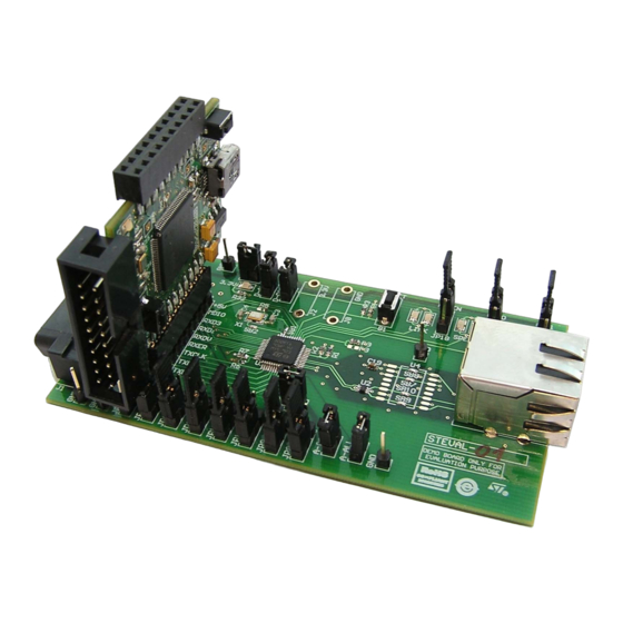
Figure 1.
ST802RT1 TX mode Ethernet PHY demonstration board - top view
Figure 2.
STM32F107 controller demonstration board - top view
Doc ID 16379 Rev 2
UM0819
User manual
®
1/37
www.st.com
Advertisement
Table of Contents

Related Manuals for ST STEVAL-PCC010V1


Summary of Contents for ST STEVAL-PCC010V1
-
Page 1: Figure 1. St802Rt1 Tx Mode Ethernet Phy Demonstration Board - Top View
ST802RT1 TX mode Ethernet PHY demonstration kit Introduction The STEVAL-PCC010V1 demonstration kit was designed to evaluate the ST802RT1 TX mode. This device is a Fast Ethernet physical layer (PHY) interface which supports 100 Base-TX and 10 Base-T applications. The PHY provides a Media Independent Interface (MII) and Reduced Media Independent Interface (RMII) for easy attachment to a 10/100 Media Access Controllers (MAC). -
Page 2: Table Of Contents
UM0819 Contents Contents Introduction ..........1 Boards key features . - Page 3 Contents UM0819 7.1.1 MII/RMII debugging connector J1 ......20 7.1.2 MII/RMII connector P1 ........21 7.1.3 RJ45 connector J9 .
- Page 4 UM0819 List of tables List of tables Table 1. Auto-negotiation jumper settings ..........16 Table 2.
- Page 5 List of figures UM0819 List of figures Figure 1. ST802RT1 TX mode Ethernet PHY demonstration board - top view ....1 Figure 2. STM32F107 controller demonstration board - top view .
-
Page 6: Boards Key Features
UM0819 Boards key features Boards key features ST802RT1 TX mode Ethernet PHY demonstration board ● ST802RT1 TX mode Fast Ethernet physical layer transceiver ● On-board 3.3 V LDO regulator ● On-board 25 MHz crystal ● 12 jumpers for boot-strap configuration (MII address, auto-negotiation, loopback, power-down, MII/RMII configuration) ●... -
Page 7: General System Description
UM0819 General system description The STEVAL-PCC010V1 ST802RT1 TX mode Ethernet PHY demonstration kit consists of two boards. The ST802RT1 TX mode demonstration board was designed to evaluate the chip. It therefore allows to easily select the PHY boot options, to evaluate the PHY boot options, to evaluate the power consumption of the chip and to attach the device to the professional test equipment. -
Page 8: Getting Started
UM0819 Getting started Getting started This section briefly describes how to start using the STEVAL-PCC010V1 ST802RT1 TX mode Ethernet PHY demonstration kit. To use this demonstration kit you must install a web browser on your computer. Package contents The ST802RT1 TX mode Ethernet PHY demonstration kit includes the following items: Hardware content ●... -
Page 9: Figure 4. St802Rt1 Tx Mode Demonstration Board Connected To Stm32F107 Demonstration
Getting started UM0819 Figure 4. ST802RT1 TX mode demonstration board connected to STM32F107 demonstration board Setup properly jumpers on the ST802RT1 TX mode Ethernet PHY demonstration board. The software does not change any settings of the PHY; it reads the settings from the PHY instead. -
Page 10: Figure 5. Network Connections Dialog Box
UM0819 Getting started Figure 5. Network connections dialog box Select IP protocol properties: select Internet Protocol (TCP/IP) and click Properties. Doc ID 16379 Rev 2 10/37 Downloaded from Elcodis.com electronic components distributor... -
Page 11: Figure 6. Internet Protocol (Tcp/Ip) Properties Dialog Box
Getting started UM0819 Figure 6. Internet Protocol (TCP/IP) Properties dialog box Change you IP settings to: IP address: 192.168.0.4 Subnet mask: 255.255.255.0 Disable firewall(s) running on your PC. 11/37 Doc ID 16379 Rev 2 Downloaded from Elcodis.com electronic components distributor... -
Page 12: Figure 7. First Page Of The Web Server Demonstration Software
UM0819 Getting started Run your web browser and open page http://192.168.0.8. You should be able to see the first page of the web server running on the demonstration kit. Figure 7. First page of the web server demonstration software You can also ping to the board using ping command on your PC. Doc ID 16379 Rev 2 12/37 Downloaded from... -
Page 13: Boards Layout
Boards layout UM0819 Boards layout Board layout - ST802RT1 TX mode Ethernet PHY demonstration board Figure 8. Board layout - ST802RT1 TX mode Ethernet PHY demonstration board 13/37 Doc ID 16379 Rev 2 Downloaded from Elcodis.com electronic components distributor... -
Page 14: Board Layout - Stm32F107 Controller Demonstration Board
UM0819 Boards layout Board layout - STM32F107 controller demonstration board Figure 9. Board layout - STM32F107 controller demonstration board Doc ID 16379 Rev 2 14/37 Downloaded from Elcodis.com electronic components distributor... -
Page 15: Configuration And Functionality
Configuration and functionality UM0819 Configuration and functionality This section describes the functions and configuration of STM802RT1A Ethernet PHY demonstration board and STM32F107 controller demonstration board. Configuration and functionality- ST802RT1 TX mode Ethernet PHY demonstration board In this chapter jumper “high” means that the jumper is placed in the position closer to the top edge of the board and “low”... -
Page 16: Table 1. Auto-Negotiation Jumper Settings
UM0819 Configuration and functionality Table 1. Auto-negotiation jumper settings Jumper Description Default configuration JP16 AN_1 High JP17 AN_0 High AN_EN - Auto-negotiation enable; when “high” - auto- JP18 High negotiation enabled, when “low” - auto-negotiation disabled 1. See functionality of AN_xxx pins in the ST802RT1 product documentation. PHY MII address The MDIO/MDC serial management interface is used to access the internal registers of the PHY. -
Page 17: Solder Bridges
Configuration and functionality UM0819 Table 4. Loopback jumper setting Jumper Description Default configuration LPBK - loopback; “high” - internal loopback selected (mainly for debug purposes); “low” - normal operation MII/RMII mode selection A strapping option allows setting the operating mode of the MAC data interface. Default operation (no pull-ups) enable normal MII mode of operation. -
Page 18: Test Point Mco
UM0819 Configuration and functionality Alternatively it is possible to change the meaning of LED1 - LED6 by writing the PHY register RN1B [0d27, 0x1B]: Table 8. LEDs functionality - alternative 2 Description Details LED1 ON for full duplex, BLINK for collision JP16 is low LED2 ON for full duplex, BLINK for collision... -
Page 19: Buttons
Configuration and functionality UM0819 6.2.2 Buttons There are two buttons on the STM32F107 controller demonstration board. The RESET button resets the STM32F107 MCU to its initial state. The B1 general purpose button is connected to PA4-pin of STM32F107 MCU and is active low. 6.2.3 LEDs There are three LEDs on the STM32F107 controller demonstration board. -
Page 20: Connectors
UM0819 Connectors Connectors Connectors of the ST802RT1 TX mode Ethernet PHY demonstration board 7.1.1 MII/RMII debugging connector J1 Figure 11. MII/RMII debugging connector J1 Table 10. MII/RMII debugging connector J1 Signal Signal Signal Signal +5 V TXCLK MDIO TXEN TXD_0 RXD_3 TXD_1 RXD_2... -
Page 21: Table 11. Mii/Rmii Connector P1
Connectors UM0819 7.1.2 MII/RMII connector P1 Figure 12. MII/RMII connector P1 Table 11. MII/RMII connector P1 Signal Signal Signal Signal RXD3 TXER TXD0 +5 V RXD0 RXER TXD3 RXD1 TXEN TXD2 MDIO RXCLK TXCLK RXD2 RXDV TXD1 7.1.3 RJ45 connector J9 Figure 13. -
Page 22: Table 13. Usb Connector Cn1
UM0819 Connectors Connectors of the STM32F107 controller board 7.2.1 USB connector CN1 Figure 14. USB connector CN1 Table 13. USB connector CN1 Signal Signal D– 7.2.2 JTAG connector CN2 The 20-pin connector (CN2) provides the JTAG interface. This interface is primarily used for communicating with a PC using suitable USB/JTAG converter box such as J-Link from IAR Systems™... -
Page 23: Table 14. Jtag Connector Cn2
Connectors UM0819 Table 14. JTAG connector CN2 Signal Signal Signal Signal RTCK connected to 3.3 V DC GND by R1 (10 kΩ) DBGRQ connected to 3.3 V DC JTMS GND by R2 (10 kΩ) JTRST JTDO DBGACK connected to JTCK GND by R14 (10 kΩ) JTDI NRST... -
Page 24: Table 15. Mii/Rmii Connector Cn3
UM0819 Connectors Table 15. MII/RMII connector CN3 Signal Signal Signal Signal RXD3 TXER TXD0 +5 V RXD0 RXER TXD3 RXD1 TXEN TXD2 MDIO RXCLK TXCLK RXD2 RXDV TXD1 7.2.4 GPIO connector CN4 Figure 18. GPIO connector CN4 Table 16. GPIO connector CN4 Signal Signal Signal... - Page 25 List of transformers and RJ45 connectors with embedded transformers with turn ratio 1.414:1 List of transformers and RJ45 connectors with embedded transformers with turn ratio 1.414:1 HALO Electronics, Inc. www.haloelectronics.com ● HFJ11-2477E-L12RL (RJ45 with integrated transformer) ● TG110-S177N2RL (transformer) Pulse www.pulseeng.com ●...
-
Page 26: Table 17. Bill Of Material St802Rt1 Tx Mode
UM0819 ST802RT1 TX mode Ethernet PHY demonstration board - BOM Appendix A ST802RT1 TX mode Ethernet PHY demonstration board - BOM Table 17. Bill of material ST802RT1 TX mode Designator Qty. Description Value Order assembled ® GM Electronic Push button (DT2112C) RESET 630-121 Farnell: 9471898... - Page 27 R34, R35 SB1, SB2, SB3, SB4, SB5, SB6, Soldering bridge Soldbridge SB4, SB5 SB7, SB8, SB9, SB10 10 / 100 Fast Ethernet ST: ST802RT1 TX ST802RT1 TX mode 3.3 V transceiver mode ESD protection, U2, U5 DVIULC6-2P6 ST: DVIULC6-2P6 DALC208SC6...
-
Page 28: Table 18. Bill Of Material Stm32F107
UM0819 STM32F107 controller demonstration board - BOM Appendix B STM32F107 controller demonstration board - Table 18. Bill of material STM32F107 Designator Qty. Description Value Order assembled Polarized capacitor C1, C2, C8 10 µF / 6.3 V Farnell: 1213794 (surface mount) C3, C4 Capacitor 100 nF_0805... - Page 29 Farnell: 1646159 GME: 630-121 Farnell: RESET1 Switch Reset 9471898 GME: 630-121 Farnell: RESET2 Switch 9471898 STM32F107_256K ST: STM32F107 Low drop voltage LD1117S33 ST: LD1117S33 regulator Epson Crystal: FA-238 25 MHz Farnell: 1712818 SB1, SB2, SB3, Solder bridge SB1, SB2 29/37...
-
Page 30: Figure 19. St802Rt1 Tx Mode Ethernet Phy Demonstration Board - Schematic - Part 1
UM0819 ST802RT1 TX mode Ethernet PHY demonstration board - schematic Appendix C ST802RT1 TX mode Ethernet PHY demonstration board - schematic Figure 19. ST802RT1 TX mode Ethernet PHY demonstration board - schematic - part 1 Doc ID 16379 Rev 2 30/37 Downloaded from Elcodis.com... -
Page 31: Figure 20. St802Rt1 Tx Mode Ethernet Phy Demonstration Board - Schematic - Part 2
ST802RT1 TX mode Ethernet PHY demonstration board - schematic UM0819 Figure 20. ST802RT1 TX mode Ethernet PHY demonstration board - schematic - part 2 31/37 Doc ID 16379 Rev 2 Downloaded from Elcodis.com electronic components distributor... -
Page 32: Figure 21. St802Rt1 Tx Mode Ethernet Phy Demonstration Board - Schematic - Part 3
UM0819 ST802RT1 TX mode Ethernet PHY demonstration board - schematic Figure 21. ST802RT1 TX mode Ethernet PHY demonstration board - schematic - part 3 Doc ID 16379 Rev 2 32/37 Downloaded from Elcodis.com electronic components distributor... -
Page 33: Figure 22. St802Rt1 Tx Mode Ethernet Phy Demonstration Board - Schematic - Part 4
ST802RT1 TX mode Ethernet PHY demonstration board - schematic UM0819 Figure 22. ST802RT1 TX mode Ethernet PHY demonstration board - schematic - part 4 33/37 Doc ID 16379 Rev 2 Downloaded from Elcodis.com electronic components distributor... -
Page 34: Figure 23. Stm32F107 Controller Demonstration Board - Schematic - Part 1
UM0819 STM32F107 controller demonstration board - schematic Appendix D STM32F107 controller demonstration board - schematic Figure 23. STM32F107 controller demonstration board - schematic - part 1 Doc ID 16379 Rev 2 34/37 Downloaded from Elcodis.com electronic components distributor... -
Page 35: Figure 24. Stm32F107 Controller Demonstration Board - Schematic - Part 2
STM32F107 controller demonstration board - schematic UM0819 Figure 24. STM32F107 controller demonstration board - schematic - part 2 35/37 Doc ID 16379 Rev 2 Downloaded from Elcodis.com electronic components distributor... -
Page 36: Table 19. Document Revision History
UM0819 Revision history Revision history Table 19. Document revision history Date Revision Changes 18-Nov-2009 Initial release. 07-May-2010 Added Section Doc ID 16379 Rev 2 36/37 Downloaded from Elcodis.com electronic components distributor... - Page 37 No license, express or implied, by estoppel or otherwise, to any intellectual property rights is granted under this document. If any part of this document refers to any third party products or services it shall not be deemed a license grant by ST for the use of such third party products or services, or any intellectual property contained therein or considered as a warranty covering the use in any manner whatsoever of such third party products or services or any intellectual property contained therein.
Need help?
Do you have a question about the STEVAL-PCC010V1 and is the answer not in the manual?
Questions and answers