Table of Contents
Advertisement
Quick Links
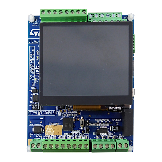
Getting started with the STEVAL-PLC001V1 industrial PLC evaluation board with
Introduction
The
STEVAL-PLC001V1
evaluation board targets compact programmable logic controller (PLC) applications in the factory
automation domain. It features a powerful human machine interface (HMI) thanks to the 3.5" TFT touchscreen mounted on the
PCB, which eases interaction with the tool.
The board implements a galvanically isolated PLC control unit with robust digital input, digital output modules, expansion
connectivity options, and interfaces.
The control unit consists of a powerful 144-pin
the TouchGFX display technology on the other side, implementing the ladder logic programming code and several additional
options.
Highly robust and reliable industrial digital input and output modules are placed symmetrically on the PCB, making the system
a 12+12 PLC, that is, a PLC GUI optimized for STM32 microcontrollers, which manages 12 industrial inputs and 12 industrial
outputs.
The 12 industrial inputs have been implemented through the combination of an eight-channel
channel
CLT03-2Q3
ICs.
The
CLT01-38SQ7
features 6.25 MHz SPI with daisy chain capability to connect, in this case, the eight-channel output
ISO8200AQ
and reverse polarity, whereas the
which can be powered from the external sensors they interface with, and the capability of running in the 60 V range for fail-safe
applications.
The 12 industrial output array consists of an eight-channel
power switch.
The
ISO8200AQ
offers a daisy-chain SPI interface and embedded galvanic insulation, separating logic and power side of 4 kV
and making the solution cost-effective (no opto-coupler is needed).
The
STEVAL-PLC001V1
also features connectivity options typical of commercial PLCs through the morpho connectors mounted
on the PCB bottom, ensuring compatibility with
The embedded ICs for industrial IO management allow great flexibility in terms of technical features, protections and embedded
diagnostics, when interfacing industrial range inputs (that is, sensors and valves) and outputs (that is, lamps, alarms, and
actuators) with the logic side.
The
STSW-PLC001
companion software package, freely available on www.st.com, allows experimenting with these advanced
features and their combination.
Thanks to this software and the smart user interface offered by the TouchGFX, you can learn how the ICs work and exploit
ready-to-use examples as well as ladder logic demonstrations and projects.
UM2933 - Rev 1 - October 2021
For further information contact your local STMicroelectronics sales office.
STM32F746ZGT7
MCU, which handles the industrial IOs on one side and
CLT03-2Q3
features two high- and low-side compatible independent channels,
ISO8200AQ
IC and a four-channel
STM32 Nucleo expansion
boards.
UM2933
User manual
HMI interface
CLT01-38SQ7
and two dual
IPS4260L
low-side intelligent
www.st.com
Advertisement
Table of Contents

Subscribe to Our Youtube Channel
Related Manuals for ST STEVAL-PLC001V1


Summary of Contents for ST STEVAL-PLC001V1
- Page 1 STSW-PLC001 companion software package, freely available on www.st.com, allows experimenting with these advanced features and their combination. Thanks to this software and the smart user interface offered by the TouchGFX, you can learn how the ICs work and exploit ready-to-use examples as well as ladder logic demonstrations and projects.
-
Page 2: Figure 1. Steval-Plc001V1 Evaluation Board
UM2933 Figure 1. STEVAL-PLC001V1 evaluation board UM2933 - Rev 1 page 2/42... -
Page 3: Getting Started
Getting started Safety precautions for use STEVAL-PLC001V1 evaluation board has a level of radiated emissions that exceeds the limit for class A devices. Therefore, the user must add a proper shielding metal enclosure (Faraday cage) in the setup of the evaluation environment of the board. -
Page 4: Figure 2. Steval-Plc001V1 Functional Block Diagram
UM2933 Hardware architecture Figure 2. STEVAL-PLC001V1 functional block diagram 12 industrial input Screw connector CLT03-2Q3 CLT03-2Q3 CLT03-38SQ7 2-ch self- 2-ch self- 8-channel high-speed powered powered Isolator opto opto SWD connector GPIO GPIO 10-pin connector SDRAM Morpho connector 128Mb 166Mz 2x38 strip male conn. -
Page 5: Board Connections And Components
UM2933 Board connections and components Board connections and components Figure 3. STEVAL-PLC001V1 external connections I0: 8 high side speed digital inputs (CTL01-38SQ7 through SPI) I0.0 I0.1 I0,2 I0.3 I0.4 I0.5 I0.6 I0.7 I1: 4 self-powered digital inputs (high/low side via CTL03-2Q3) -
Page 6: Figure 4. Steval-Plc001V1 Top Components
UM2933 Board connections and components Figure 4. STEVAL-PLC001V1 top components CLT01-38SQ7 (U1) - high speed 8 digital inputs current limiter on SPI CLT03-2Q3 (U4,U5) - self-powered digital input current limiter EMIF08-LCD04M16 - 8-line L-C EMI filter and ESD protection for display interfaces... -
Page 7: Main Components
UM2933 Main components Figure 5. STEVAL-PLC001V1 bottom components Morpho connector Morpho connector STM32F746ZGT7 (U27) - high-performance and DSP with FPU Arm Cortex-M7 MCU Flash memory Isolation boundary MCU reset switch (S2) Main components 1.5.1 CLT01-38SQ7 CLT01-38SQ7 is the 8-channel current limiter termination with high-speed SPI interface. The... -
Page 8: Iso8200Aq
8-bit fault register (where the OVT faults of each channel are stored). The two stages communicate through the galvanic isolation channel via an ST proprietary protocol. Active channel current limitation (OVL) combined with thermal shutdown (OVT), independent for each channel, protects the device against overload and overtemperature. -
Page 9: Digital Inputs And Outputs
Q1. Input and output terminals are placed symmetrically. Power distribution on the board STEVAL-PLC001V1 evaluation board is designed to work with 24 V nominal power supply. The MCU and logic circuit are galvanically isolated from the field side circuit. -
Page 10: External Memory Interface
Open load detection feature is activated by placing proper resistors between LOADx and PGND ground plane. In the STEVAL-PLC001V1 evaluation board, there are resistors placed for open load detection for the Q1.X four outputs. For Q1.2 and Q1.3, instead, they are activated only if J8 and J9 jumpers are closed. Thus, the Fault LED (D22) might glow when there is no load connection or partial connection to output terminals. -
Page 11: How To Run The Evaluation Board With The Preloaded Firmware
(24 V) placed in the bottom-left corner: this option offers the complete experience with the STEVAL-PLC001V1, that is all programming/debugging and display features can be executed, and the industrial I/O can be handled with the highest possible current ratings allowed by the ICs (i.e. -
Page 12: Firmware Overview And Architecture
UM2933 Firmware overview and architecture Firmware overview and architecture STSW-PLC001 companion software package is available for download at www.st.com. It is designed as a development tool for industrial PLCs. To use the STEVAL-PLC001V1 board and the associated firmware, power supply the board (24 V or through a portable USB power supply) and play with the user interface powered by the TouchGFX technology featuring HMI capabilities. -
Page 13: Schematic Diagrams
Schematic diagrams Figure 8. STEVAL-PLC001V1 circuit schematic (1 of 9) GND_Logic GND_Logic SPI2_MISO DI_I1_1 SPI2_MISO SPI2_MISO DI_I1_1 DI_I1_1 GND_Logic PD6/B2 DI_I1_2 24V_Field GND_Logic PD6/B2 PD6/B2 DI_I1_2 DI_I1_2 24V_Field 24V_Field SPI2_NSS DI_I1_3 GND_Field 24V_Field SPI2_NSS SPI2_NSS DI_I1_3 DI_I1_3 GND_Field GND_Field SPI2_SCK... -
Page 14: Figure 9. Steval-Plc001V1 Circuit Schematic (2 Of 9)
Figure 9. STEVAL-PLC001V1 circuit schematic (2 of 9) TP14 C1 33pF 220R 220R220R220R CLT01-38SQ7 C2 33pF GND_CLT1 GREEN GREEN 33pF GREEN GREEN 33pF GREEN GREEN VDD_CLT GREEN GREEN GND_CLT1 GND_Field GND_Field R60E INPUT CLT01_38SQ7_TR I0 .0 CLT_IN1 Data out= /MISO... -
Page 15: Figure 10. Steval-Plc001V1 Circuit Schematic (3 Of 9)
Figure 10. STEVAL-PLC001V1 circuit schematic (3 of 9) CLT03-2Q3 Isolation Barrier R197 U4 CLT03-2Q3 OUTP1 OUTP1 I1.0H R23 0E C19 10nF C19 10nF INATTL1 ANODE1 OUTN1 OUTN1 DI_I1_1 VBUF1 CATHODE1 OUTP1 OUTN2 OUTN2 DI_I1_2 INA1 OUTP1 CATHODE2 OUTN1 OUTN1 ANODE2 10nF I1.0L... -
Page 16: Figure 11. Steval-Plc001V1 Circuit Schematic (4 Of 9)
Figure 11. STEVAL-PLC001V1 circuit schematic (4 of 9) ISO8200AQ 24V_Field 4.7uF/63V 10pF D24 GREEN Q0.7 7.5K DO_Q0_EN 22nF GND_Field Isolation Barrier Q0.7 Q0.7 D25 GREEN Q0.6 7.5k ISO8200AQ 22nF D26 GREEN OUT2_1 Q0.6 Q0.5 7.5K Q0.6 OUT2_2 ESDALC6V1-1M2 22nF OUT_EN OUT3_1 Q0.5... -
Page 17: Figure 12. Steval-Plc001V1 Circuit Schematic (5 Of 9)
Figure 12. STEVAL-PLC001V1 circuit schematic (5 of 9) 24V_Field 24V_Field IPS4260L Isolation Barrier 7.5K 7.5K 7.5K 7.5K GREEN GREEN 5V_Field GND_Field GREEN PGND1 PGND4 BAT20JFILM GREEN DO_Q1_1 PGND2 PGND3 510R 100nF ANODE1 IN1_FLT 330R 5.1K Q1.3 CATHODE1 LOAD1 GND_Logi c... -
Page 18: Figure 13. Steval-Plc001V1 Circuit Schematic (6 Of 9)
Figure 13. STEVAL-PLC001V1 circuit schematic (6 of 9) STM32F746ZGTx DO_LCD_BL_CTRL U27A STM32F746ZGT7 R184 RED.R2 R152 FMC_CTRL.NBL0 FMC_ADD.A10 R153 0E M O- A3 3030TR FMC_CTRL.NBL1 FMC_ADD.A11 SPI2_ISO_MOSI USB.OVER_CURRENT U27C M O- A1 DI_I1_1 SPI5_HOLD USB.POW ER_SW ITCH_ON C100 STM32F746ZGT7 DI_I1_2 SPI2_MORPHO_MOSI FMC_ADD.BA_0... -
Page 19: Figure 14. Steval-Plc001V1 Circuit Schematic (7 Of 9)
Figure 14. STEVAL-PLC001V1 circuit schematic (7 of 9) Morpho & Memory IS42S32400F-7TLI-TR Morpho Connectors VSS_3 FMC_DATA.D0 FMC_DATA.D15 DQ15 100nF VDDQ VSSQ_7 FMC_DATA.D1 FMC_DATA.D14 DQ14 100nF FMC_DATA.D2 FMC_DATA.D13 GND_Logic DQ13 con38-2x19-strip-male (MORPHO) VSSQ VDDQ_7 FMC_DATA.D3 FMC_DATA.D12 con38-2x19-strip-male (MORPHO) DQ12 UART5_RX R104 NM... -
Page 20: Figure 15. Steval-Plc001V1 Circuit Schematic (8 Of 9)
Figure 15. STEVAL-PLC001V1 circuit schematic (8 of 9) LED+ LED+ 600 Ohms LQH32PN3R3NN0L STPS1L40M C128 3. 3uH, 1A 4.7uF 10nF 100nF 10nF 10nF 4.7uF GND_LCD TP11 RSET DO_LCD_BL_CTRL 2STR1160 STLD40DPUR 10_1% GND_LCD 100K 600 Ohms GND_Logi c GND_LCD LCD_RED2 LCD_RED3... -
Page 21: Figure 16. Steval-Plc001V1 Circuit Schematic (9 Of 9)
Figure 16. STEVAL-PLC001V1 circuit schematic (9 of 9) Power Provision for different footprint DC-DC CONVERTER Isolation 24V_Field terminal block STL42P6LLF6 NCS1S2405SC SF-0603HI700M-2 (7A FUSE) GND_Logic +VOUT +VIN 24V_Field -VOUT -VIN 100Ohms CTRL GND_Field SMAJ15A-TR R142 R143 CON2 4n7/3kV 7.5k 4.7uF... -
Page 22: Bill Of Materials
UM2933 Bill of materials Bill of materials Table 2. STEVAL-PLC001V1 bill of materials Item Q.ty Ref. Value Description Manufacturer Part Number Battery Keystone 3030TR holder (not 3030TR Electronics mounted) C1 C2 C3 C4 33 pF, 0402 (1005 Ceramic C53 C54 C55... - Page 23 UM2933 Bill of materials Item Q.ty Ref. Value Description Manufacturer Part Number 1 pF, 0402 (1005 C32 C33 C38 Ceramic Metric), 10 V, Wurth Elektronik 885012005001 capacitors 1 µF, 0402 (1005 Ceramic C34 C86 Metric), 50 V, Taiyo Yuden UMK105CBJ105KV-F capacitors 100 nF, 0402 C36 C89...
- Page 24 UM2933 Bill of materials Item Q.ty Ref. Value Description Manufacturer Part Number Capacitor 220 µF SMD, C110 (not Wurth Elektronik - 6032-28, 10 V mounted) 1 µF, 0402 (1005 Ceramic C104 C111 Metric), 6.3 V, Taiyo Yuden JMK105BJ105KV8F capacitors 4.7 pF NPO - +0.25 pF, 0402 Ceramic C124 C125...
- Page 25 UM2933 Bill of materials Item Q.ty Ref. Value Description Manufacturer Part Number 40 V, 1 A STPS1L40M, STmite low DO-216AA, 460 drop power STPS1L40M mV @ 1 A Schottky rectifier SMAJ15A-TR, 400 W TVS DO-214AC, SMA, SMAJ15A-TR in SMA 400 W SM15T33CA, 1500 W, 33 V SMCJ33CA-TR...
- Page 26 UM2933 Bill of materials Item Q.ty Ref. Value Description Manufacturer Part Number 4.7 µH, 1210 Fixed Murata LQH32PN4R7NN0L (3225 Metric), 1 A inductor 100 Ohms, 3312 (8530 metric), 10 Ferrite bead Wurth Elektronik 74279225101 A, +/-25% 220 Ohms, 0805 L5 L7 Ferrite beads Murata BLM21PG221SN1D (2012 Metric), 2 A...
- Page 27 UM2933 Bill of materials Item Q.ty Ref. Value Description Manufacturer Part Number 120E, 0402 (1005 Chip Metric), 50 V, R18 R130 resistors (not Yageo RC0402FR-13120RL 0.063 W, 1/16 W, mounted) +/-1% 120E, 0402 (1005 R20 R21 Metric), 50 V, Chip resistor R155 0.063 W, 1/16 W, +/-1%...
- Page 28 UM2933 Bill of materials Item Q.ty Ref. Value Description Manufacturer Part Number R65 R100 R101 R103 R107 R110 R111 R112 R114 R116 10 K, 0402 (1005 R117 R119 Metric), 50 V, Chip Yageo RC0402FR-7D10KL R120 R124 0.063 W, 1/16 W, resistors R125 R127 +/-1%...
- Page 29 UM2933 Bill of materials Item Q.ty Ref. Value Description Manufacturer Part Number R152 R160 0 0402 (1005 Chip R161 R163 Metric) 50 0.063 resistors (not Yageo RC0402FR-070RL R184 R206 W, 1/16 W ±1% mounted) 51E, 0402 (1005 Metric), 50 V, R172 Chip resistor Yageo...
- Page 30 UM2933 Bill of materials Item Q.ty Ref. Value Description Manufacturer Part Number Quad low- IPS4260L, 20- side TSSOP (0.173", IPS4260L intelligent 4.40mm Width) power switch Galvanic isolated octal high side ISO8200AQ, smart power ISO8200AQ TFQFPN32 solid state relay with SPI interface White LED STLD40DPUR, 8- power supply...
- Page 31 UM2933 Bill of materials Item Q.ty Ref. Value Description Manufacturer Part Number 200 mA low LDK220M33R, quiescent SC-74A, current and LDK220M33R SOT-753, low noise SOT23-5L ILD207T, 8-SOIC Vishay (0.154", 3.90 mm Opto-isolator Semiconductor ILD207T Width) Opto Division REM2-2405S, DC DC 0.86"...
-
Page 32: Regulatory Compliance
UM2933 Regulatory compliance Regulatory compliance Formal Notice Required by the U.S. Federal Communications Commission FCC NOTICE: This kit is designed to allow: (1) Product developers to evaluate electronic components, circuitry, or software associated with the kit to determine whether to incorporate such items in a finished product and (2) Software developers to write software applications for use with the end product. -
Page 33: Board Versions
UM2933 Board versions Board versions Table 3. STEVAL-PLC001V1 versions Finished good Schematic diagrams Bill of materials STEVAL$PLC001V1A STEVAL$PLC001V1A schematic diagrams STEVAL$PLC001V1A bill of materials 1. This code identifies the STEVAL-PLC001V1 evaluation board first version. UM2933 - Rev 1 page 33/42... -
Page 34: Appendix Amcu Interfaces Mapped With Devices And Board Terminal Blocks
UM2933 MCU interfaces mapped with devices and board terminal blocks Appendix A MCU interfaces mapped with devices and board terminal blocks Table 4. List of MCU interfaces mapped with devices and board terminal blocks Device Board Other MCU side Jumper Devices Device pins side test... - Page 35 UM2933 MCU interfaces mapped with devices and board terminal blocks Device Board Other MCU side Jumper Devices Device pins side test Jumpers interface interface devices test point description point SPI2_NSS,S PB12,PB1 PI2_SCK,SPI 3,PC1,PC 2_MOSI, SPI2_MISO Q0.0,Q0.1, Q0.2,Q0.3, Q0.4, Q0.5,Q0.6, Q0.7 OUT8_1 &...
- Page 36 UM2933 MCU interfaces mapped with devices and board terminal blocks Device Board Other MCU side Jumper Devices Device pins side test Jumpers interface interface devices test point description point (PA1,PB0, PA5,PC0, PD1,PG7), RED (R2- (PA6,PG1 R7), GREEN 0,PB10,P (G2-G7), B11,PC7, BLUE (B2- PD3), (PG11,PG...
-
Page 37: Appendix B Options For Customization
UM2933 Options for customization Appendix B Options for customization STEVAL-PLC001V1 board can be customized by soldering or changing mounted components and implementing the related changes in the firmware. Daisy chain connection on the STM32F746ZG SPI2 peripheral STM32F746ZG is the master in a daisy chain connection where the CLT01-38SQ7, the... -
Page 38: Revision History
UM2933 Revision history Table 5. Document revision history Date Revision Changes 25-Oct-2021 Initial release. UM2933 - Rev 1 page 38/42... -
Page 39: Table Of Contents
UM2933 Contents Contents Getting started ..............3 Safety precautions for use . -
Page 40: List Of Tables
STEVAL-PLC001V1 bill of materials ........ -
Page 41: List Of Figures
STEVAL-PLC001V1 functional block diagram ........ - Page 42 ST’s terms and conditions of sale in place at the time of order acknowledgement. Purchasers are solely responsible for the choice, selection, and use of ST products and ST assumes no liability for application assistance or the design of Purchasers’...
Need help?
Do you have a question about the STEVAL-PLC001V1 and is the answer not in the manual?
Questions and answers