Table of Contents
Advertisement
Quick Links
Getting started with the STEVAL-PTOOL2V1 compact reference design for
medium voltage brushless power tools based on STSPIN32F0252
Introduction
The
STEVAL-PTOOL2V1
is a ready-to-use reference design tailored for medium voltage power tools driven by 3-phase
brushless motors and supplied from 8S to 15S batteries. It can also effectively be used in other battery-operated applications
requiring similar architecture, rating and performance.
The
STEVAL-PTOOL2V1
is based on the
®
‑M0 STM32 MCU and
Cortex
The power stage can be populated with any power MOSFET with similar ratings and hosted in a powerFLAT 5x6 package.
The board has a single shunt sensing topology. Field-oriented control (FOC) and sensored or sensorless 6-step control
implementation allows driving permanent magnet synchronous motors (PMSMs) and brushless DC (BLDC) motors.
This reference design can deliver up to 19 A of continuous current with very good thermal dissipation performance thanks to the
mounted heat-sink. It is compatible with a wide range (from 20 to 72 V
the
VIPER013BLS
in buck configuration to generate +12 V and +3.3 V supply voltage required by the application.
The
STEVAL-PTOOL2V1
embeds a potentiometer for speed variation and is fully protected from thermal shutdown,
undervoltage lockout and overcurrent.
It comes in a compact layout of 80 x 58 mm and includes the
position feedback from Hall effect sensors.
The
STSW-PTOOL2V1
firmware can be debugged and configured through an external
LINK/V3MINI).
UM2772 - Rev 1 - October 2020
For further information contact your local STMicroelectronics sales office.
STSPIN32F0252
STL130N8F7
MOSFETs.
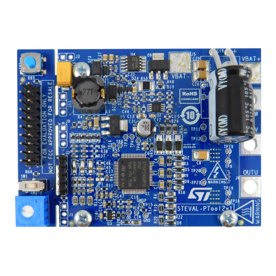
Figure 1.
STEVAL-PTOOL2V1 evaluation board
motor controller which embeds a 3-phase 250 V gate driver, a
) input voltage and includes a power supply stage with
DC
STSW-PTOOL2V1
six-step companion firmware that uses the
ST-LINK
UM2772
User manual
debugger
(ST-LINK/V2-1
or
ST-
www.st.com
Advertisement
Table of Contents

Subscribe to Our Youtube Channel
Related Manuals for ST STEVAL-PTOOL2V1


Summary of Contents for ST STEVAL-PTOOL2V1
-
Page 1: Figure 1. Steval-Ptool2V1 Evaluation Board
UM2772 User manual Getting started with the STEVAL-PTOOL2V1 compact reference design for medium voltage brushless power tools based on STSPIN32F0252 Introduction STEVAL-PTOOL2V1 is a ready-to-use reference design tailored for medium voltage power tools driven by 3-phase brushless motors and supplied from 8S to 15S batteries. It can also effectively be used in other battery-operated applications requiring similar architecture, rating and performance. -
Page 2: Getting Started
UM2772 Getting started Getting started Safety precautions Danger: There is danger of serious personal injury, property damage or death due to electrical shock and burn hazards if the kit or components are improperly used or installed incorrectly. Warning: • The kit is not electrically isolated from the high-voltage supply AC-DC input. •... -
Page 3: Overview
UM2772 Overview Overview STEVAL-PTOOL2V1 features: • 20 to 72 V input voltage • Up to 250 V high voltage rail (limited to 100 V by on-board components) • Up to 19 Arms output current • STSPIN32F0252 featuring: – 250 V, 1 A 3-phase gate driver –... -
Page 4: Installing The Board
UM2772 Installing the board Installing the board • The installation and cooling down of the evaluation board must be in accordance with the specifications and target application • The motor drive converters must be protected against excessive strain. In particular, components should not be bent or isolating distances altered during transportation or handling •... -
Page 5: Hardware Description And Configuration
UM2772 Hardware description and configuration Hardware description and configuration Figure 2. STEVAL-PTOOL2V1 circuitry main blocks - top view SWD, UART, GPIOs Power supply Feedback network STSPIN32F0252 UM2772 - Rev 1 page 5/28... -
Page 6: Figure 3. Steval-Ptool2V1 Circuitry Main Blocks - Bottom View
UM2772 Hardware description and configuration Figure 3. STEVAL-PTOOL2V1 circuitry main blocks - bottom view Power stage Shunt resistor Heat sink mounting hole Heat sink mounting hole Heat sink mounting hole Heat sink mounting hole UM2772 - Rev 1 page 6/28... -
Page 7: Table 1. Jumper Settings
UM2772 Hardware description and configuration Figure 4. STEVAL-PTOOL2V1 main components and connectors J3 external trigger VBAT- VBAT+ J8 W phase J7 V phase J6 U phase J2 Hall encoder connector J1 external speed regulation potentiometer TR1 speed regulation trimmer SW1 spinning direction switch... -
Page 8: Table 2. Connectors And Test Points
UM2772 Hardware description and configuration Table 2. Connectors and test points Name Label Description 1-2-3 External potentiometer connector (remove R70 if used) A+/H1 B+/H2 Hall/encoder sensor connector Z+/H3 Hall sensor/encoder supply External trigger switch VBAT+ Battery positive terminal VBAT- Battery negative terminal OUT U OUT V 3-phase BLDC motor phases connections... -
Page 9: Table 3. Test Points
UM2772 Hardware description and configuration Table 3. Test points Name Label Description W phase high side gate OUT3 W phase RES3 RES2 W phase low side gate RES1 SENSE PB4 MCU GPIO V phase high side gate TP10 TP10 V phase TP11 TP11 V phase low side gate... -
Page 10: How To Use The Board
Sensorless mode To configure the STEVAL-PTOOL2V1 evaluation board for 6-step sensorless mode, BEMF network components (R65, R66, R67) have to be mounted and the BEMF detection network must be enabled. You have to set jumpers as follows: •... -
Page 11: Hall/Encoder Motor Speed Sensor
UM2772 Hall/encoder motor speed sensor Hall/encoder motor speed sensor STEVAL-PTOOL2V1 evaluation board supports the digital Hall and quadrature encoder sensors for motor position feedback. Sensors can be connected to the STSPIN32F0252 through J2 connector as listed in the following table. -
Page 12: Overcurrent Detection And Current Sensing Measurement
UM2772 Overcurrent detection and current sensing measurement Overcurrent detection and current sensing measurement STEVAL-PTOOL2V1 evaluation board implements overcurrent protection based on the STSPIN32F0252 integrated comparator. The single shunt resistor measures the load current bringing the voltage signal associated to the load current and amplified by U2B OpAmp to CIN pin (TP22). -
Page 13: Bus Voltage Circuit
UM2772 Bus voltage circuit Bus voltage circuit STEVAL-PTOOL2V1 evaluation board provides the bus voltage sensing. This signal is set through voltage dividers (R71 and R72) from motor supply voltage (VBAT) and sent to PA7 GPIO (ADC channel 7) of the embedded MCU. -
Page 14: Hardware User Interface
ST-LINK/V2-1 to J11 SWD connector. Figure 6. STEVAL-PTOOL2V1 detachable section Turn on/off circuitry The board offers the possibility of connecting or disconnecting the battery to the circuitry via an external switch (J3), to reduce the quiescent consumption to a very low level. -
Page 15: Keep-Alive Circuit
UM2772 Turn on/off circuitry Figure 7. Turn on/off trigger circuitry STN3P10F6 VBAT Driver and logic power supply BZT585B15T 1uF/100V 1uF/100V GPIO input (trigger monitor) BAT46JFILM N.M. BAT30 BSS123W GPIO output (keep-alive circuit) R690R KSC7xxJ 1nF/100V N.M. 7.2.1 Keep-alive circuit As soon as the Q8 PMOS connects the battery to the buck regulator, the power-up sequence starts, and V are provided to the STSPIN32F0252 driver and MCU, respectively. -
Page 16: Debug
UM2772 Debug Debug STEVAL-PTOOL2V1 evaluation board can be connected to an external ST-LINK/V2-1 debugger/programmer which features: • USB software re-enumeration • Virtual COM port interface on USB connected to the STSPIN32F0252 (UART1) PB6/PB7 pins • Mass storage interface on USB... -
Page 17: Schematic Diagrams
Schematic diagrams Figure 8. STEVAL-PTOOL2V1 circuit schematic (1 of 2) OUTU SWD connector N.M. N.M. N.M. OUTV VBAT OUTW J 11 N.M. S TP S 1H100MF 6 7 8 TP 1 4.7R BAT54J 100nF/10V 100nF/10V 100nF/10V STL130N8F7 J 10 S TRIP 2x10... -
Page 18: Figure 9. Steval-Ptool2V1 Circuit Schematic (2 Of 2)
Figure 9. STEVAL-PTOOL2V1 circuit schematic (2 of 2) P AO_BEMF OUTU BAT30 J P 2 J 2 1 A+/H1_C P AO_BEMF A+/H1 B+/H2 B+/H2_C Z+/H3 P A1_BEMF P A0 OUTV VHALL Z+/H3_C BZT585B3V3T VHALL 100pF/10V P A2_BEMF OUTW N.M. N.M. -
Page 19: Bill Of Materials
UM2772 Bill of materials Bill of materials Table 5. STEVAL-PTOOL2V1 bill of materials Item Q.ty Ref. Part/Value Description Manufacturer Order code C1, C2, C3, 100 nF/10 SMT Ceramic 885012206020 or C12, C16, Wurth Elektronik V/X7R 0603 Capacitor equivalent C18, C20 C4, C7, C11, 1 µF/50 V/X5R... - Page 20 UM2772 Bill of materials Item Q.ty Ref. Part/Value Description Manufacturer Order code 3.3 nF/10 V/X7R SMT ceramic 885012206011 or Wurth Elektronik 0603 capacitor equivalent 1 nF/10 V/NPO SMT ceramic 0603 capacitor STPS1H100MF High voltage STmite flat power Schottky STPS1H100MF (DO222-AA) rectifier D1, D4, D7 High efficiency...
- Page 21 UM2772 Bill of materials Item Q.ty Ref. Part/Value Description Manufacturer Order code Wire Wound #B966BS-271M=P3 or 270uH Ferrite Inductor Murata Equivalent for Power Lines NCP18XH103F03RB or NTC1 10 k ±1% 0603 NTC Thermistor Murata Equivalent Net1, Net2 N.M. (not mounted) N-channel 80 V, 3.0 mOhm typ., STL130N8F7...
- Page 22 UM2772 Bill of materials Item Q.ty Ref. Part/Value Description Manufacturer Order code R31, R32, R33, R48, 10 k 0603 SMT resistor R49, R51 R40, R41, R42, R58, 1.5 k 0603 SMT resistor 100 k 0603 SMT resistor 0 R 0805 SMT resistor 12 k 0603 SMT resistor...
- Page 23 UM2772 Bill of materials Item Q.ty Ref. Part/Value Description Manufacturer Order code Trimming 3386P-1-104-LF or 100 k 3386P Bourns potentiometer Equivalent 250 V three- STSPIN32F0252 phase controller TQFP64-10x10x with ARM Cortex STSPIN32F0252TR MCU-1 A capability Dual rail-to-rail TSV912 input/output 8 TSV912IST TSV912IYST MiniSO8...
-
Page 24: Revision History
UM2772 Revision history Table 6. Document revision history Date Version Changes 02-Oct-2020 Initial release. UM2772 - Rev 1 page 24/28... -
Page 25: Table Of Contents
UM2772 Contents Contents Getting started ..............2 Safety precautions . -
Page 26: List Of Tables
STEVAL-PTOOL2V1 bill of materials ........ -
Page 27: List Of Figures
STEVAL-PTOOL2V1 main components and connectors........ - Page 28 ST’s terms and conditions of sale in place at the time of order acknowledgement. Purchasers are solely responsible for the choice, selection, and use of ST products and ST assumes no liability for application assistance or the design of Purchasers’...
Need help?
Do you have a question about the STEVAL-PTOOL2V1 and is the answer not in the manual?
Questions and answers