Advertisement
Quick Links
UM3374
User manual
Getting started with the STEVAL-PTOOL4A reference evaluation board
Introduction
The
STEVAL-PTOOL4A
reference evaluation board is a compact system designed to control BLDC/PMSM motors in a battery-
operated systems. The board is powered by the STM32G473CET6 MCU along with the STDRIVE101 3-phase gate drive
control IC to drive six STL220N6F7 power MOSFETs. The board is empowered with the STM32 motor control ecosystem for
PMSM/BLDC motors. The board supports CAN, USART, SPI, and I²C interfaces to support a wide range of data logging and
communication interfacing options.
This reference design is ideal for high-performance motor control applications in power tools such as drill machines, grinders,
disc cutters, circular saws, leaf blowers, handheld mowers, etc. The small form factor and ample computing power make it
suitable even for applications such as drones, wheelchairs, home appliances, and robotic platforms.
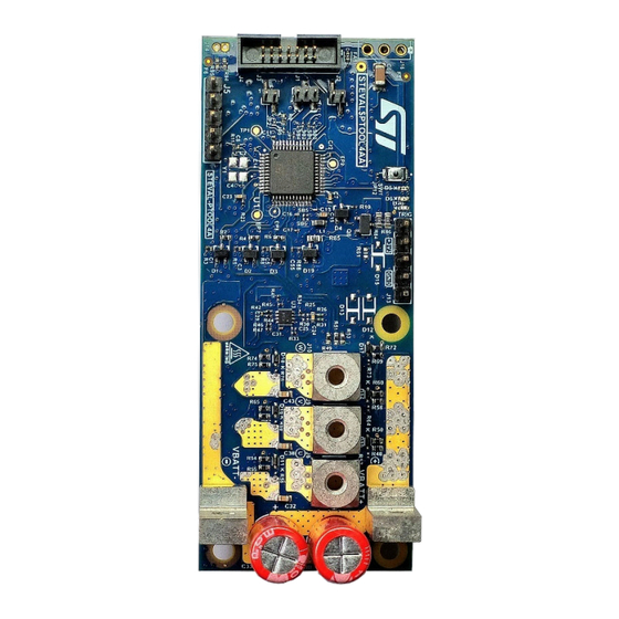
Figure 1.
STEVAL-PTOOL4A board
Notice:
For dedicated assistance, submit a request through our online support portal at www.st.com/support.
UM3374 - Rev 1 - October 2024
www.st.com
For further information contact your local STMicroelectronics sales office.
Advertisement

Subscribe to Our Youtube Channel
Related Manuals for ST STEVAL-PTOOL4A


Summary of Contents for ST STEVAL-PTOOL4A
- Page 1 Figure 1. STEVAL-PTOOL4A board Notice: For dedicated assistance, submit a request through our online support portal at www.st.com/support. UM3374 - Rev 1 - October 2024 www.st.com For further information contact your local STMicroelectronics sales office.
- Page 2 UM3374 Main features (key features) Main features (key features) • Suitable for applications up to 250 W • 12-28 V operation (nominally 21 V) • 20 A maximum output RMS current • SPI, USART, I²C communication interfaces and provision for CAN bus signals •...
- Page 3 Resale of ST products with provisions different to the information set forth herein voids any warranty granted by ST for such product. ST and the ST logo are trademarks of ST. All other product or service names are the property of their respective owners.
- Page 4 UM3374 Development tools Development tools Hardware requirements • STLINK-V3SET debugger and programmer for STM32/STM8. • USB 2.0 Type B micro USB cable. • Throttle/potentiometer (optional). Software tool requirements • STM32 motor control software for development kit (X-CUBE-MCSDK-6) • • STMicroelectronics - STM32CubeIDE –...
- Page 5 Quick start Quick start Follow the sequence below to configure the STEVAL-PTOOL4A board. The board is preprogrammed for sensorless speed control operation of the EMAX-1500 BLDC drone motor. To use the EMAX-1500 BLDC motor, it can be driven just by connecting a 30 kΩ potentiometer at throttle terminal J13 (refer to the schematics and Appendix A for details).
- Page 6 3, and Figure 4 help to locate these features on the STEVAL-PTOOL4 board. Figure 3. System block diagram (functional block diagram) Figure 4. STEVAL-PTOOL4A top view (signal connections) Microcontroller unit (STM32G473CET6) ® ® Based on the high-performance Arm Cortex -M4 32-bit RISC core, the STM32G473CET6 operates at a frequency of up to 170 MHz.
- Page 7 UM3374 Hardware description It features a QUADSPI flash memory interface, and an extensive range of enhanced I/Os and peripherals connected to two APB buses, two AHB buses, and a 32-bit multi-AHB bus matrix. The devices embed peripherals allowing mathematical/arithmetic function acceleration (CORDIC for trigonometric functions and FMAC unit for filter functions).
- Page 8 The input DC voltage (V ) is a key parameter of the STEVAL-PTOOL4A, which requires constant monitoring as its value is crucial in determining the various conditions of the control mechanism involved in the development board. This function is realized by a voltage divider circuit connected to the VDC and whose output is maintained across the capacitance C55 along with a diode protection circuit.
- Page 9 Latch enable circuit (optional) STEVAL-PTOOL4A comes with an ON-OFF latch circuit for the DC-DC converter to keep the board powered only for a short duration as per need. But this circuit is bypassed and not the default configuration. To enable this feature, R82 must be removed.
- Page 10 System operation To operate the STEVAL-PTOOL4A board with the PMSM/BLDC motor, the 18 V-24 V DC input is connected at the DC input connectors and the three phase terminals of the motor is connected at three phase connectors of the board.
- Page 11 In the Inverter section, the user-imported board can be selected for STEVAL-PTOOl4A. UM3374 - Rev 1...
- Page 12 UM3374 System operation Figure 8. List of motors A GUI appears which shows the motor control circuit and motor section. Here, the user can change the switching frequency, speed sensing method, etc. Figure 9. Interface to generate the source code The source code can be generated by clicking on Generate the Project.
- Page 13 On a Windows machine this can be done by checking Ports in device manger ( go to Windows Start-> Device Manager->Ports). Note Com poert No. (COMx). Next ST Motor Pilot can be launched. Upon opening if there is a "Discover Board" option this can be used to find the board. Otherwise UART dropdown menu can be used to do COM port selection option.
- Page 14 Schematic diagrams Figure 11. STEVAL-PTOOL4A circuit schematic (1 of 6) VBATT+ +3V3A +3V3 VBATT+ TRIG_X +3V3A +3V3 H2_X H1_X SPI_MISO H3_X SPI_MOSI NRST THROTTLE_X SPI_CS TRIG_X SPI_CLK SWCLK TEMP_FB TEMP_FB DIR_X SWDIO ADC_VDC ADC_VDC CAN1TX/I2C SDA ADC_I_U ADC_I_U CAN1RX/I2CSCL ADC_I_V...
- Page 15 Figure 12. STEVAL-PTOOL4A circuit schematic (2 of 6) ADC_I_U 1 of 2 PC13 ADC_I_V PC13 OP3_OUT_CPIN PC14-OSC32_IN MCU_TRIG LED_INFO/H3 ADC_V_U LED_INFO PC15-OSC_OUT TEMP_FB CAN1RX/I2CSCL PF0-OSC_IN ADC_V_V SPI_CLK/H2 PF1-OSC_OUT SPI_CLK PG10/NRST PA10 BKIN2 PA11 SPI_CS/H1 PB8/BOOT0 PA12 SPI_CS SWDIO PA13 SWCLK...
- Page 16 Figure 13. STEVAL-PTOOL4A circuit schematic (3 of 6) +3V3A I SENSE U BEMF SENSING 6-STEP SINGLE SHUNT +3V3 OP1_INP OP1_OUT BEMF_U OUT_U BEMF_V SENP_U OUT_V +3V3A +3V3A ADC_I_U BEMF_W NTC1 OUT_W PLACED CLOSE TO OUTPUT TERMINALS TSV912IQ2T SENM_U OP1_INM TEMP_FB...
- Page 17 Figure 14. STEVAL-PTOOL4A circuit schematic (4 of 6) VBATT+ 82.5K 402K EN_BUCK 10pF EN/CLKIN(*) FB/VOUT AGND 27uH BOOT PGND 470 OHM 470 OHM 121K L6981NDR 100nF 22uF 10uF 1uF/50V Vbatt to +5V DC-DC GND_SIGNAL VBATT+ +3V3 +3V3A VOUT BEAD 100nF...
- Page 18 Figure 15. STEVAL-PTOOL4A circuit schematic (5 of 6) BAT54K 22ohm VBATT+ REG12 OUT_U 4.7uF 100nF 4.7uF BAT54K 100nF 22ohm GHS1 SRC_UL HIN1 BOOT1 HIN2 OUT1 HIN3 GLS1 +3V3 BAT54K LIN1 GHS2 LIN2 BOOT2 OUT_V LIN3 OUT2 GLS2 GHS3 OP3_OUT_CPIN BAT54K...
- Page 19 Figure 16. STEVAL-PTOOL4A circuit schematic (6 of 6) VBATT+ STL220N6F7 STL220N6F7 STL220N6F7 OUT_W OUT_U OUT_V 220nF 220nF 220nF OUT_W1 STL220N6F7 STL220N6F7 C33B OUT_V1 C33A OUT_U1 STL220N6F7 180uF 180uF SRC_UL SRC_WL SRC_VL 0612_TINDROP 0612_TINDROP R_SH_U+ NET_TIE SB10 NET_TIE SENP_V SENP_W SENP_U...
- Page 20 UM3374 Bill of materials Bill of materials Table 3. STEVAL-PTOOL4A bill of materials Item Q.ty Ref. Part/value Description Manufacturer Order code C1 C3 C5 C6 C11 CAPACITOR C12 C13 C14 C21 100nF, 0201, Wurth CERAMIC 885012104001 C28 C31 C35 C46...
- Page 21 UM3374 Bill of materials Item Q.ty Ref. Part/value Description Manufacturer Order code CAPACITOR 22uF, 1210, Wurth CERAMIC 885012209074 25V, +/-10% Elektronik SMD 1210 CAPACITOR 1uF, 0805, 50V, Wurth CERAMIC 885012207103R +/-10% Elektronik SMD 0805 CAPACITOR 4.7nF, 0201, Wurth CERAMIC 885012104008 25V, +/-10% Elektronik SMD 0201...
- Page 22 UM3374 Bill of materials Item Q.ty Ref. Part/value Description Manufacturer Order code CONN HEADER Wurth J5 J13 250V, 3A 61300511121 2.54MM STR Elektronik 5POS CONN Battery+, Wurth J6 J7 HEADER R/A 7461101 Battery-, 100A Elektronik 6POS, M3 OUT_U1, CONN Wurth J8 J9 J10 OUT_V1, HEADER R/A...
- Page 23 UM3374 Bill of materials Item Q.ty Ref. Part/value Description Manufacturer Order code CHIP R2 R4 R6 R49 R51 27k, 0402, 50V, RESISTOR Bourns CR0402-FX-2702GLF 62.5mW, +/-1% SMD 1% 1/16W 0402 CHIP 3.9k, 0201, RESISTOR R3 R5 R8 R88 25V, 50mW, Yageo AF0201FR-073K9L SMD 1%...
- Page 24 UM3374 Bill of materials Item Q.ty Ref. Part/value Description Manufacturer Order code CHIP RESISTOR R57 R59 R61 DNM, 0402 SMD 1% 1/8W RC0201FR-07220RL 0402 (not assembled) CHIP 39k, 0201, 25V, RESISTOR Yageo RC0201FR-0739KL 50mW, +/-1% SMD 1% 1/20W 0201 CHIP RESISTOR 10K, 0201, 25V, SMD 1%...
- Page 25 UM3374 Bill of materials Item Q.ty Ref. Part/value Description Manufacturer Order code 75R, 0402 CHIP (1005 Metric), RESISTOR R94 R95 Bourns CR0402-FX-75R0GLF 50V, 62.5mW, SMD 1% +/-1% 1/16W 0402 4.7K, 0402 CHIP (1005 Metric), RESISTOR Bourns CR0402-FX-4701GLF 50V, 62.5mW, SMD 1% +/-1% 1/16W 0402 CHIP...
- Page 26 STEVAL-PTOOL4A versions PCB version Schematic diagrams Bill of materials STEVAL$PTOOL4AA schematic diagrams STEVAL$PTOOL4AA bill of materials STEVAL$PTOOL4AA 1. This code identifies the STEVAL-PTOOL4A evaluation board first version. The STEVAL$PTOOL4AA code is printed on the board. UM3374 - Rev 1 page 26/41...
- Page 27 UM3374 Regulatory compliance information Regulatory compliance information Notice for US Federal Communication Commission (FCC) For evaluation only; not FCC approved for resale FCC NOTICE - This kit is designed to allow: (1) Product developers to evaluate electronic components, circuitry, or software associated with the kit to determine whether to incorporate such items in a finished product and (2) Software developers to write software applications for use with the end product.
- Page 28 1. Set the input DC voltage range in the power supply within 19 V - 23 V. 2. Set the current range in the power supply within 1.5 Amp - 5 Amp. 3. Connect the power supply +VE and -VE with the STEVAL-PTOOL4A board’s +Vbatt and -Vbatt respectively, as shown in figure 2.
- Page 29 Running preprogrammed firmware 6. Connect the 3-phase EMAX motor with the board (as shown in figure below). 7. Connect the potentiometer’s respective pins with STEVAL-PTOOL4A j13 pinouts 3.3.v, GND, and the Throttle pin respectively (as shown in figure below). Figure 18.
- Page 30 UM3374 Running preprogrammed firmware When the board is initially powered, both the LEDs are switched on for 2-3 s. After this, if the red LED blinks it implies some error. Ideally, the green LED should blink to show readiness upon rotating the potentiometer, the motor is actuated and starts to rotate at a speed proportional to potentiometer input.
- Page 31 To generate Firmware for STEVAL-PTOOL4A in older version of MCSDK environment , a board descriptor JSON file of the STEVAL-PTOOL4A board for MCSDK version such as Ver6.3.0 (or Ver6.2.1). This file contains the control circuit-related information viz Pin mapping of PWM/ADC/Hall sensor/GPIOs, type of current sensing and OP-AMP gains etc.
- Page 32 UM3374 Possible customisations Appendix C Possible customisations Following Customization are possible. However appropriate precautions must be taken. Increase Input supply voltage The board is designed for nominal input of 21V. However, if required the board can be utilized with higher Voltage say upto 32V.
- Page 33 UM3374 Possible customisations Figure 23. Connection of an external DC-DC converter board Increase effective power ratings The effective Power rating of board can be improved by providing thermal relief through a heat sink. Possible Sample is shown below for reference users are advised to crosscheck all the dimensions. Actual design can also consider the heat sink thermal capability depending on application and duty cycle etc.
- Page 34 UM3374 Possible customisations Figure 24. Mounting of a heat sink Users can choose heat sink dimensions and shape as per the requirement. The dimensions of heat sink user in figure above is given as reference below: UM3374 - Rev 1 page 34/41...
- Page 35 UM3374 Possible customisations Figure 25. Dimensions of the sample heat sink (see above figure) UM3374 - Rev 1 page 35/41...
- Page 36 UM3374 Revision history Table 5. Document revision history Date Revision Changes 10-Oct-2024 Initial release. UM3374 - Rev 1 page 36/41...
- Page 37 STEVAL-PTOOL4A JSON file ........
- Page 38 Generation of Code with MCSDK V6.3.0 ........31 Source code generation from ST motor control workbench (MCSDK) ....31 Appendix C Possible customisations .
- Page 39 STEVAL-PTOOL4A bill of materials ........
- Page 40 STEVAL-PTOOL4A top view (power connections) ........
- Page 41 ST’s terms and conditions of sale in place at the time of order acknowledgment. Purchasers are solely responsible for the choice, selection, and use of ST products and ST assumes no liability for application assistance or the design of purchasers’...
Need help?
Do you have a question about the STEVAL-PTOOL4A and is the answer not in the manual?
Questions and answers