
Related Manuals for Alfa IN SVAROG 320 HD PULSE MODULAR


Summary of Contents for Alfa IN SVAROG 320 HD PULSE MODULAR
- Page 1 WELDING MACHINE SVAROG 320 HD PULSE MODULAR OPERATING MANUAL ALFA IN a.s. © www.alfain.eu SVAROG 320 HD PULSE modular manual EN 01...
-
Page 2: Table Of Contents
13 MMA WELDING (ELECTRIC WELDING - ELE) ............28 14 MAINTENANCE AND SERVICE TESTS ..............28 15 ECODESIGN OF WELDING EQUIPMENT ............... 32 16 DISPOSAL OF ELECTRICAL WASTE ............... 32 17 WARRANTY LETTER .................... 33 ALFA IN a.s. © www.alfain.eu... -
Page 3: Introduction
3/33 INTRODUCTION Dear consumer, Company ALFA IN a.s. thanks you for buying our product and believe that you will be satisfied with our machine. Welding machine may be operated only by trained persons and only in the technical provisions. Company ALFA IN a.s. accept no responsibility for damage caused by improper use. -
Page 4: Safety Precautions
4. When handling the machine with a lifting device, hook the machine on all crane eyes. Other mounting is not permitted! 5. Disconnect the device from the mains before carrying out any work on the electrical system, removing the cover or cleaning it. ALFA IN a.s. © www.alfain.eu... -
Page 5: Operating Conditions
The manufacturer is not liable for damage caused by improper use and operation. Only use original ALFA IN spare parts for maintenance and repair. 2. The device complies with EN 61000-3-12 under the following conditions:... - Page 6 Due to the size of the installed capacity, the approval of the distribution plants must be required to connect the equipment to the public distribution network. We warn the user that he is responsible for any interference from welding. ALFA IN a.s. © www.alfain.eu...
-
Page 7: Technical Data
7/33 TECHNICAL DATA SVAROG 320 HD PULSE MODULAR Method MIG/MAG Mains voltage V/Hz 3x400/50-60 Welding current range 30/15,5 - 320/30,0 20/20,8 - 300/32,0 Open-circuit voltage U 60,0 Mains protection 16 @ Max. effective current I 15,1 14,1 1eff Welding current (DZ=100%) I... -
Page 8: Machine Accessories
If you decide to use a torch other than the one above, you must select according to the current range used and the torch load time. ALFA IN a.s. is not responsible for damage to welding torches due to overload. -
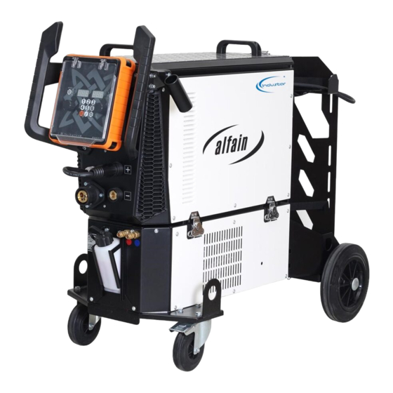
Page 9: Machine Description And Functions
9/33 MACHINE DESCRIPTION AND FUNCTIONS MAIN PARTS OF THE MACHINE Image 1 - Main machine parts Item. Description Control panel Connection cable (re-polarity) Euro torch connector ALFA IN a.s. © www.alfain.eu... - Page 10 A11 and disconnect the connector A15 (electrical connection between the CU and the generator). The generator can then be easily manipulated. WIRE FEED MECHANISM Item. Description Pressure arm nut Pressure arm Bovden boot EURO connector Pulley Figure 2 - Four-fold scroll ALFA IN a.s. © www.alfain.eu...
- Page 11 11/33 SELECTING A FEED PULLEY All ALFA IN MIG/MAG machines use double groove pulleys. These grooves are designed for two different wire diameters (e.g. 0.8 and 1.0 mm). The wire feed pulleys must be suitable for the diameter and material of the welding wire.
- Page 12 3. Cut the end of the wire attached to the edge of the coil and feed it into the bovden E3 through the pulleys E5 and about 5 cm inside the EURO ALFA IN a.s. © www.alfain.eu...
- Page 13 In the extreme case, the motor may be completely blocked and the gearbox will be unduly mechanically stressed, the electric motor and the power output of the controller will be overloaded and may be damaged. Clean the pulleys of canned oil before starting. ALFA IN a.s. © www.alfain.eu...
- Page 14 4. After a prolonged machine shutdown or torch change, it is advisable to purge the pipe with shielding gas before welding. Item. Description Bottle Bottle valve Reducing valve High pressure manometer Low pressure manometer Adjusting screw Gas valve Figure 6 - Gas flow settings ALFA IN a.s. © www.alfain.eu...
- Page 15 15/33 WATER TORCH COOLING SYSTEM 1. The cooling unit is located at the bottom of the machine. 2. The pump seal in this ALFA IN welder is specially designed for ACL-10 fluid (pink, order 4600, canister. Operating range - ambient temperature -10 °C to +40 °C).
-
Page 16: Basic Settings
E.466. BASIC SETTINGS DESCRIPTION OF THE CONTROL PANEL Figure 7 - Control Panel Item. Description Button: gas test Button: Pulse mode LED - shines when PULSE mode is selected. Quick JOB selection ALFA IN a.s. © www.alfain.eu... - Page 17 The synergy curves are welded in the PB position (fillet weld, horizontal, inclined from above). For welding in other positions, parameter correction is necessary. AXE 250-320 PULSE SMART (AL) ø 0.8 ø 1.0 ø 1.2 SG/Fe With 82% CO SG/Fe With 92% CO ALFA IN a.s. © www.alfain.eu...
- Page 18 0 mΩ to 60 mΩ - these values are not important for the user, factory setting CrE = 10 mΩ, the value can be set badly with the V16 encoder). 8. If an error occurs, Err is displayed on the right display of V11, the measurement must be repeated. ALFA IN a.s. © www.alfain.eu...
- Page 19 If the V17 and V19 lights are on, the machine is set to two-stroke stair mode. The first stroke means to press the torch button and keep it pressed, the machine will start welding with the starting current SCu for the starting current t ALFA IN a.s. © www.alfain.eu...
- Page 20 The difference of the BILEVELU compared to the classical steps is in the second stroke, when by quickly pressing and releasing the torch button the machine switches between the two set main welding currents. Figure 8 - Mode curves ALFA IN a.s. © www.alfain.eu...
- Page 21 Parameters marked 4 are only available in 4T-stairs mode. COUNTER OF WELDING HOURS The data can be displayed at any time if you have entered the Secondary Parameters menu. Long press button V4 (1) to display the welding time in hours. ALFA IN a.s. © www.alfain.eu...
- Page 22 - button V13), JOB SYN: Power, Correction/Damping (selectable depending on machine settings - button V13), JOB Switch between the individual JOBS using the H6 (+) and H7 (-) buttons The LOCK button locks/unlocks the UP/DOWN and M buttons ALFA IN a.s. © www.alfain.eu...
- Page 23 The information shown on the H2 display. J.xx JOB switching (xx - JOB number). Inductance value setting [Inductance] (SYN/MAN). I.xx Only for machines with new software version. The machine is in ELECTRODE mode, the buttons do not respond. ALFA IN a.s. © www.alfain.eu...
-
Page 24: Mig/Mag Synergy Welding
If a torch with remote control is connected, its display shows machine power (current, wire feed speed, material thickness), correction (voltage, wire feed speed), choke value or JOB. Use the UP/DOWN buttons to adjust the displayed value, use the MODE button to switch between functions. ALFA IN a.s. © www.alfain.eu... -
Page 25: Pulse Mode
5. Select the setting and display of the voltage or choke by long pressing the V13 button. 6. Press the V20 button to switch between 2T/4T modes. 7. During the welding process, the welding current is displayed on V10 and the voltage is displayed on V11. ALFA IN a.s. © www.alfain.eu... -
Page 26: Mma Welding (Electric Welding - Ele)
Figure 10 - Distance of the tube from the material MMA WELDING (ELECTRIC WELDING - ELE) 1. Select the MMA method according to SELECTION OF THE WELDING METHOD. 2. Disconnect the connecting cable A2, connect the electrode holder to the quick connector A8. ALFA IN a.s. © www.alfain.eu... -
Page 27: Consumption Tables
TABLE OF GAS CONSUMPTION DURING WELDING Gas consumption per 1 hour Wire diameter [mm] Gas flow [l/min] of welding [l/hour] 6 * 60 = 360 8 * 60 = 480 10 * 60 = 600 12 * 60 = 720 ALFA IN a.s. © www.alfain.eu... -
Page 28: Mma Welding (Electric Welding - Ele)
3. Once or twice a year, blow out the entire plant with pressurised air, especially the aluminium cooling profiles. Beware of the risk of damage to electronic components by direct compressed air from a short distance! ALFA IN a.s. © www.alfain.eu... - Page 29 Fit the correct pulley. diameter of the welding wire. Poor quality welding Check and replace if wire. necessary. Bovden in the torch is Check and replace if dirty or defective. necessary. ALFA IN a.s. © www.alfain.eu...
- Page 30 The groove on the feed pulley does not correspond to the Fit the correct pulley. The welding wire diameter of the welding is removed by wire. sliding. Adjust the pressure Poor top pulley according to these pressure. instructions. ALFA IN a.s. © www.alfain.eu...
- Page 31 31/33 STATEMENT OF WARRANTY 1. In accordance with the warranty periods stated below, ALFA IN guarantees the proposed product to be free from defects in material or workmanship when operated in accordance with the written instructions as defined in this operating manual.
-
Page 32: Ecodesign Of Welding Equipment
The company ALFA IN a.s. is registered in the LIST of the collective system EKOLAMP s.r.o. (under the producer registration number 06453/19-ECZ). This symbol on products or in accompanying documents means that used electrical and electronic products must not be added to normal municipal waste. -
Page 33: Warranty Letter
The warranty certificate is the proof of purchase (invoice) with the serial number of the product or the warranty certificate below filled in by the authorised dealer. Production number: Day, month in words and year of sale: Stamp and signature of the seller: ALFA IN a.s. © www.alfain.eu...
Need help?
Do you have a question about the SVAROG 320 HD PULSE MODULAR and is the answer not in the manual?
Questions and answers