Table of Contents
Advertisement
Quick Links
Advertisement
Table of Contents

Related Manuals for Hilti DSW 1510-CA


Summary of Contents for Hilti DSW 1510-CA
- Page 1 DSW 1510-CA English...
- Page 3 DSW 1510-CA Original operating instructions...
-
Page 5: Table Of Contents
3.1.1 System components ........11 3.1.2 DSW 1510-CA drive unit ....... . . 12 3.1.3 Transport devices . - Page 6 4.4 DST WRC-CA wireless remote control unit ......16 4.5 Noise emission values ........16 4.6 DSW-SPP 240 single-pulley stand .
-
Page 7: Information About The Documentation
Care and maintenance ........32 9.1 Cleaning drive unit . -
Page 8: Symbols In The Illustrations
Instructions for use and other useful information Dealing with recyclable materials Do not dispose of electric equipment and batteries as household waste 1.2.3 Symbols in the illustrations The following symbols are used in illustrations: These numbers refer to the corresponding illustrations found at the beginning of these operating instructions The numbering reflects the sequence of operations shown in the illustrations and may deviate from the steps described in the text... -
Page 9: Product Information
The type designation and serial number are printed on the rating plate. ▶ Write down the serial number in the table below. You will be required to state the product details when contacting Hilti Service or your local Hilti organization to inquire about the product. - Page 10 Electrical safety ▶ Power tool plugs must match the outlet. Never modify the plug in any way. Do not use any adapter plugs with earthed (grounded) power tools. Unmodified plugs and matching outlets will reduce risk of electric shock. ▶ Avoid body contact with earthed or grounded surfaces, such as pipes, radiators, ranges and refrigerators.
-
Page 11: Proper Arrangement Of The Workplace
Use a dust-extraction device wherever possible. To achieve a high level of dust extraction, use a suitable vacuum extractor of a type that is recommended by Hilti for wood dust and/or mineral dust and which is designed for use with this power tool. -
Page 12: Protection Against Electric Shock
▶ Damaged or faulty switches must be replaced at a Hilti service center. Do not use a machine, power tool or appliance that cannot be switched on and off at the main switch. -
Page 13: Safety Concept For Working With Wire Saws
▶ Do not start work until the drive unit and the pulley stands have been securely and firmly secured to a solid sub-base. A toppling or dropped part can result in serious damage or injury. ▶ Connect the electric power and compressed air supply only once the wire saw has been set up completely. -
Page 14: Description Of The Danger Zone
2.5.1 Description of the danger zone The danger zone for wire saws includes zones in which: • (A) Persons could be hit by a whipping diamond wire. • (B) Persons could be hit by flying parts. 2.5.2 Danger zone A (shown here colored yellow) Protection against whipping diamond wire. -
Page 15: Description
Hilti specialist on the safe application of these instructions. The operator in charge must be aware of the possible dangers and of his responsibility for safety, both with regard to himself and to others. The operator is responsible for securing the danger area by cordoning it off and taking protective measures (guards, etc.) as necessary. -
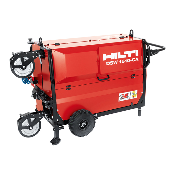
Page 16: Dsw 1510-Ca Drive Unit
3.1.2 DSW 1510-CA drive unit Guide pulley (slack-wire side) Drive motors Guide pulley (taut-wire side) Connections, water supply for water nozzles Drive pulleys Starting lock Wire storage pulleys (fixed) § Compressed-air cylinder guide Wire storage pulleys (movable) & Compressed-air cylinder Box for electrical components 3.1.3 Transport devices... -
Page 17: Operating Panel
3.1.4 Operating panel Main switch Antenna & Connection for remote control Connection, compressed-air hose cable Connection, main water supply 'Wire tension' operating button Guard (electricity connection) LED light Connection, power supply § 3.1.5 DSW-SPP 240 pulley stand Pulley cover with adapter for cool- Anti-twist locking pin &... -
Page 18: Items Supplied
"users" below, are permitted to operate the wire saw. These persons must be completely familiar with the content of these operating instructions and must have been trained in safe operation by a Hilti specialist. The user in charge must be aware of the possible dangers and of his responsibility for safety, both with regard to himself and to others. -
Page 19: Technical Data
Net wire storage capacity 32 ft - 2 in (9.8 m) Technical data DSW 1510-CA drive unit Dimensions (L x W x H) 63.8 in x 30.9 in x 38.6 in (1,620 mm x 785 mm x 980 mm) Weight... -
Page 20: Dst Wrc-Ca Wireless Remote Control Unit
The wire saw is designed for use with diamond wires in the 8 mm to 12 mm diameter range. At special request, the product can be configured by the manufacturer for use with thicker diamond wires. For more information visit www.hilti.group or contact your Hilti specialist for diamond cutting equipment. English... -
Page 21: Accessories For Diamond Wire Saws
2048471 (US) Accessories and wear parts for the wire saw system Hilti approved wear parts and other accessories for your product can be found in your local Hilti Store or at: www.hilti.group Preparations at the workplace Planning and safety 6.1.1 Planning the cuts to be made... -
Page 22: Safety Aspects To Be Clarified Prior To Installation
Arrange the cutting sequence so that the diamond wire cannot become trapped by parts that are cut away. ▶ Plan the sequence of operations before setting up the system. ▶ Plan the cooling water supply system and water disposal system. ▶... - Page 23 Vertical cut (release pulley) Fast cutting process with high load and lesser longevity of diamond wires Horizontal cut Doorway cut, right Doorway cut, bottom Doorway cut, top 2238935 English *2238935*...
-
Page 24: Determination Of Storage Capacity Needed And Necessary Wire Length
Doorway cut, left Column cut using the hor- izontal/vertical sawing de- vice Beam cut with horizon- tal/vertical device Plunge cut Bottom cut with plunge cut device using the plunge pulley accessory Determination of storage capacity needed and necessary wire length Key: •... -
Page 25: Power Source
Approximate calculations Required wire storage capacity Wire length ×2 4.4 + × 2 Power source Fuse rating Make sure that the site-provided electricity supply, regardless of whether it is from the electricity grid or from a generator, incorporates a ground conductor and ground fault circuit interrupter and that these components are correctly connected. -
Page 26: Requirements To Be Met By The Cooling Water Supply
▶ When working outdoors, use only extension cables that are approved and corre- spondingly marked for this application. Recommended minimal gauge (conductor cross section) and maximum exten- sion cable length Extension cable AWG 12 AWG 10 AWG 8 AWG 6 Conductor cross sec- 3.3 mm²... -
Page 27: Setting Up Drive Unit
▶ Use only anchors suitable for the base material to secure the pulley stands. Comply with the instructions for use in the operating instructions of the anchor. In principle, the Hilti HKD M16 metal expansion anchor is suitable for setting as anchor in concrete to secure the equipment. An alternative method of attachment might be necessary however, depending on circumstances. -
Page 28: Connecting The Electricity Supply, Water And Compressed Air
WARNING Risk of injury! Risk of injury if the pulley stand falls! ▶ Use only anchors suitable for the base material to secure the pulley stands. Comply with the instructions for use in the operating instructions of the anchor. 1. Mark the position of the anchor hole for the pulley stand. 2. -
Page 29: Pairing Dst Wrc-Ca Wireless Remote Control
1. Set up the drive unit on the jobsite. → page 23 2. Connect a cooling-water hose to the inlet on the drive unit and to an outlet of the on-site water supply. 3. Connect both cooling-water hoses to distributors (A) and (B). 4. -
Page 30: Diamond Wire
Diamond wire 7.3.1 Fitting wire connectors and connection of diamond wire Read and follow the instructions given in the operating instructions of the diamond wire and the connectors. 7.3.2 Diamond-wire path and cutting direction The illustration shows the path of the diamond wire through the structure and the drive unit in the cutting direction. -
Page 31: Check Of Diamond Wire / Guide Pulley Alignment (Slack-Wire Side)
4. From the rear of the structure, feed the diamond wire back through the second hole (3). 5. Feed the diamond wire through the hollow axle of the pulley stand (taut-wire side) (4). 6. Open the cover of the drive unit. 7. -
Page 32: Tensioning Diamond Wire
7.3.5 Tensioning diamond wire 1. Lay the diamond wire on the drive pulleys and the pulleys of the wire storage unit. → page 26 2. Set the main switch to ON. 3. Switch the air compressor on. 4. Tension the diamond wire by pressing the Wire tension operating button on the drive unit. -
Page 33: Operation
▶ Comply with the instructions for installation in the operating instructions of the guards. Operation Checks before beginning sawing Before starting operations with the wire saw, clarify the following safety aspects: ▶ Has the danger area been correctly defined and has it been ensured that these areas are not entered during operation? ▶... -
Page 34: During Operation Of The Wire Saw
During operation of the wire saw DANGER Serious injury hazard! Risk of injury due to entry into the danger zone or unforeseen situations. ▶ Press the EMERGENCY STOP button immediately if a dangerous, unforeseen or critical situation arises (e.g. if the diamond wire jumps off a guide pulley or if a person enters the danger zone). -
Page 35: Changing Storage Levels
Changing storage levels When the cylinder reaches its maximum stroke the wire storage unit is full and you have to resume operation using the lay on a new wire storage level. The drive has a limit switch that stops the drive automatically when it is reached. •... -
Page 36: Care And Maintenance
To help ensure safe and reliable operation, use only genuine Hilti spare parts and consumables. Spare parts, consumables and accessories approved by Hilti for use with the product can be found at your local Hilti Store or online at: www.hilti.group. Cleaning drive unit... -
Page 37: Blow Remaining Traces Of Water Out Of The Cooling Water Circuit And Motors
Carrying out maintenance Comply with the instructions for use in the operating instructions of the grease gun. 1. Position the compressed-air cylinder with the piston rod fully extended. 2. Clean the piston rods with a cloth and Hilti spray. 2238935 English... -
Page 38: Replacing Rubber-Tired Pulleys On The Dsw-Spp 240 Single-Pulley Stand
3. Move the piston to make sure that you also clean the areas of the piston rod covered by the guide bearings. 4. Connect the tube of the grease gun to the grease nipple. 5. Inject grease into the 2 grease nipples. Continue injecting grease until the grease squeezes out at the piston rods. -
Page 39: Transport And Storage
11.Use a suitable screwdriver to tighten the screws (8 TX 45 screws) of the locating ring to 25 Nm. ▶ The pulley is serviced and ready for installation. Transport and storage Transport ▶ Use the grips provided for transportation. Keep the grips clean and free from oil and grease. -
Page 40: Troubleshooting Table
1. Disengage the lock securing the transport handle. 2. Swing the transport handle into a horizontal position. ▶ The teeth of the lock are securely intermeshed. 3. Tighten the lock of the transport handle. 4. Insert the lifting bar into the socket at the swivel mechanism. 5. - Page 41 Trouble or fault Possible cause Action to be taken The wire saw doesn’t A new sawing wire jams in a ▶ Complete the cut with the start. kerf made by a worn sawing worn sawing wire or use a wire. thinner sawing wire.
-
Page 42: Fault Codes
Very abrasive material. ▶ Use different sawing wire specifications. Fault codes Note down the fault code when you contact Hilti Service. This will make trou- bleshooting and fault rectification easier. Malfunction Possible cause Action to be taken Er100: Connection to Paired partner device not ▶... -
Page 43: Disposal
Most of the materials from which Hilti tools and appliances are manufactured can be recycled. The materials must be correctly separated before they can be recycled. In many countries, your old tools, machines or appliances can be returned to Hilti for recycling. Ask Hilti Service or your Hilti representative for further information. -
Page 44: Fcc Statement (Applicable In Us)/Ic Statement (Applicable In Canada)
Changes or modifications not expressly approved by Hilti can restrict the user’s right to operate the device. Manufacturer’s warranty ▶ Please contact your local Hilti representative if you have questions about the warranty conditions. English 2238935 *2238935*... - Page 48 *2238935* 2238935 Hilti = registered trademark of Hilti Corp., Schaan 20210317...
Need help?
Do you have a question about the DSW 1510-CA and is the answer not in the manual?
Questions and answers