Table of Contents
Advertisement
Quick Links
Advertisement
Chapters
Table of Contents

Related Manuals for Hilti DS WS15


Summary of Contents for Hilti DS WS15
- Page 1 DS WS15 Operating instructions...
-
Page 2: Table Of Contents
ORIGINAL OPERATING INSTRUCTIONS Contents 1. General information 3 –4 2. Description 5–12 3. Tools and accessories 13–16 4. Technical data 17–20 5. Safety precautions 21–25 6. Preparing the saw system for use 27–37 7. Operating the equipment 39–41 8. Care and maintenance 43–48 9. -
Page 3: General Information
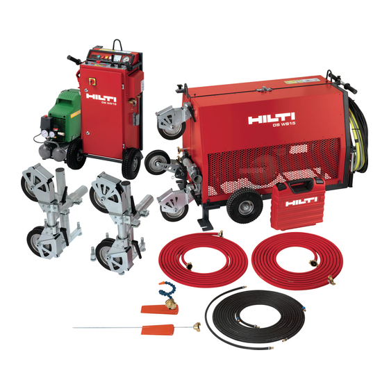
1. General information Safety notices and their meaning Symbols The operating instructions must be read carefully before the equipment is put into operation. Always keep these operating instructions with the equipment. The wire saw system should be handed over to other Read the operating Return waste instructions before... - Page 4 1. General information Drive unit with 2 motors, wire storage unit, guide pulleys, wheel assembly and electric cable for connection to the control unit Control unit Air compressor Air hoses (2×7 m, 1×1 m) Single pair pulley stand Water nozzle – long Water nozzle –...
-
Page 5: Description
2. Description Description 2.1 Areas of application 2.2 DS WS15 basic system units 2.3 Operating controls 2.4 Drive principle 2.5 Saw advance and wire storage 2.6 Wire guidance 2.7 Safety concept for the working area... -
Page 6: Description
2. Description Toolbox containing accessories and tools Areas of application The DS WS 15 is an electrically-powered wire saw which, Long water supply nozzle by means of its diamond wires, is capable of sawing For use at the rear of the object being cut, deep in the through construction materials ranging from heavily saw kerf. - Page 7 2. Description T–shaped transportation handle, pull-out type Folding transportation handle Transportation or lifting lever for raising the wheels Lifting points for transportation by crane 2 water connections for cooling water supply to the diamond wire 2 baseplates for securing the drive unit to the floor or ground Cable and hose storage compartment 400 V electric cables for drive motors...
- Page 8 2. Description Wire clamping vice Drive wheel 1, 280 mm dia., fixed Drive wheel 2, 280 mm dia., moving, for saw advance Storage pulleys, 280 mm dia., moving, for saw advance Storage pulleys, 200 mm dia., fixed, for wire storage Compressed air cylinder stop piece Tension-side guide pulley, adjustable in direction and position...
- Page 9 2. Description Protective cover securing latch Operating controls DS WS 15 control unit Ventilation grille 400 V, 32 amp socket, supply to the drive motors 24 V control circuit socket for the drive unit Compressed air supply, supply from the compressor 2 compressed air connections, supply to the drive unit Transportation and lifting bars...
- Page 10 2. Description 12 13 Control unit cover lock Regulator for wire drive speed of rotation (controls Key for control unit cover lock cutting speed, see DS WS 15 main power switch Drive ON, green light Digital display for wire cutting speed in m/s Drive OFF, red button Green “Ready for operation”...
-
Page 11: Drive Principle
2. Description Drive principle The wire is driven by 2 electric motors fitted with drive tem are designed to achieve high initial torque and work- wheels. The diamond wire is fed around the drive wheels ing torque. in the form of a figure eight to ensure optimum grip. The The wire speed can be infinitely adjusted within the motors’... -
Page 12: Wire Guidance
2. Description Wire guidance Guide pulleys are fitted on the wire tension side and on the return side (slack side). The wire is guided to the object being sawn by way of these guide pulleys which can be adjusted in any direction. Wire guides in the form of single- or twin-pair pulley stands, plunge pulleys etc., are mounted at the start and end of the cut. -
Page 13: Tools And Accessories
3. Tools and accessories Tools and accessories 3.1 Diamond wires 3.2 Accessories for connecting wires 3.3 Accessories for securing the drive unit and wire guides 3.4 DS-WSRW release pulley 3.5 DS-WSPW plunge pulley 3.6 DS-WSVC vertical sawing device 3.7 DSW-WG wire guard... - Page 14 ■ Hilti diamond wires of the standard 11 mm diame- ter are available in fixed lengths of 10 m, 14 m, 18 m, 22 m, 26 m and 30 m (other lengths and oth- er diameters on request).
- Page 15 Water connection nipple Water supply GK seal Water seal for 356700/5 Steel wedge Securing concrete blocks Accessories and wearing parts for Hilti wire saw systems Ordering Quantity designation M12L clamping spindle, long Fastening pulley stand, drive unit HKD-D M12×50 flush anchor...
- Page 16 3. Tools and accessories DS-WSRW release pulley DS-WSVC vertical sawing device Item no. 315834 Item no. 339312 Used in many applications for cutting through very thick For simple, fast cuts directly below the wire drive unit. walls or where long cuts have to be made. The release No further pulleys or wire guidance system is then used pulley ensures optimum wire contact length and thus a (no single-pair pulley stand).
-
Page 17: Technical Data
4. Technical data Technical data 4.1 Power supply 4.2 Dimensions and weights 4.3 Insulation class 4.4 Climatic conditions for operation and storage 4.5 Technical data 4.6 Noise values 4.7 Rating plates... -
Page 18: Technical Data
Dimensions 520×590×1080 mm Weight approx. 68 kg Single-pair pulley stand Dimensions 460×240×560 mm Weight approx. 23 kg Compressor The compressor supplied by Hilti with the equipment or any other compressor that complies with the specified technical data may be used. -
Page 19: Insulation Class
4. Technical data Insulation class Drive: protection against water jets (use of high-pressure cleaning systems is not permissible) Control unit: protection against water spray (use of high-pressure cleaning systems is not permissible) Climatic conditions for operation and storage – The data specified for the DS WS 15 wire saw is guaranteed up to a height of 2000 m above sea level. –... -
Page 20: Noise Values
4. Technical data Compressor Compressed air Min. 6 bar Air volume Min. 100 l/min Supply connection 230 V Noise values Equipment: DS WS 15 electric wire saw Sound pressure level as per DIN EN ISO 3744 * < 79 dB(A) * Measured at a distance of 2.8 m from the drive unit Rating plates for drive unit and control unit... -
Page 21: Safety Precautions
5. Safety precautions Safety precautions 5.1 Safety measures at the working area 5.2 Preparations 5.3 Securing the objects being cut and disposal of sawing slurry 5.4 Use of the equipment as directed, operating safety 5.5 Electrical safety 5.6 Safety precautions during transport 5.7 General safety information... -
Page 22: Safety Precautions
5. Safety precautions Approval must be obtained from the site engineer or Safety measures at the working area architect prior to carrying out drilling and sawing work. ■ Safety measures must be implemented in the area where ■ Make sure that no gas, water, electricity or other sup- sawing is taking place so that operators and third parties ply lines are located in the cutting area. -
Page 23: Use Of The Equipment As Directed, Operating Safety
Hilti specialist. ■ Check that the wire saw and its components , the saw- ing wire and wire connectors and all accessories are in good condition and perfect working order before use. -
Page 24: Electrical Safety
In case of faults or malfunctions, the wire ■ Always avoid adopting a bent-over body position saw should be repaired by an authorised Hilti repair mechan- when carrying heavy items, i.e. keep your back straight ic or qualified electrical specialist. -
Page 25: General Safety Information
Contact with or inhalation of the dust may cause been trained to use the equipment safely by a Hilti spe- allergic reactions and/or respiratory diseases to the cialist. All warnings and safety information must be operator or bystanders. -
Page 27: Preparing The Saw System For Use
6. Preparing the saw system for use Preparing the saw system for use 6.1 Planning the wire guidance system 6.1.1 Positioning the wire guide pulleys 6.1.2 Wire pressure 6.2 Drilling through holes for the wire 6.3 Setting up the electric supply 6.4. -
Page 28: Preparing The Saw System For Use 6.1 Planning The Wire Guidance System
6. Preparing the saw system for use 6.1.2 Planning the wire guidance system Wire pressure α0 ■ Before installing the wire saw, you must carefully =90° study the situation and plan the wire guides, the drilling α1 =70° of through-holes, the sequence of the work and the pro- α2 cedure involved. -
Page 29: Transporting The Wire Saw
6. Preparing the saw system for use id ground on its transportation wheels (located in line with the centre of gravity) by means of the pull-out T- bar located at the rear. The wheels can be brought from ■ The 5-pole, 400V socket on the control unit may not the standing position to the transport position (and vice versa) by one person without any trouble by means of be changed or replaced by another type. -
Page 30: Securing The Wire Guides And Saw Drive Unit
Under certain conditions it may be necessary to use an alternative fastening method. Please contact Hilti Technical Service if you have any questions about secure fastening. Clamping nut with swivelling baseplate... -
Page 31: Rigging And Tensioning The Wire
6. Preparing the saw system for use ■ Install the water supply with a feed of at least 5 lt. / ■ Important: When the wire is threaded through, atten- min at a max. water pressure of 6 bar for the DS WS 15 tion must be paid to correct direction of travel. - Page 32 6. Preparing the saw system for use nected with the pin provided. The vice mounted on the sion side in the corresponding storage position. Pass front of the drive unit is designed to hold the wire secure- the wire around the storage pulleys in one or more turns, ly and thus makes this operation easier.
- Page 33 6. Preparing the saw system for use guide pulleys. Make sure that the guide pulleys on the pulley stands are aligned with the drive unit. Exact align- ment has been achieved when the wire runs in the cen- tre of the guide pulleys. ■...
-
Page 34: Setting Up The Wire Cooling System
6. Preparing the saw system for use Setting up the wire cooling system Basic applications ■ Ideally, hoses should be 6.9.1 Standard vertical cut led from the 2 water con- ■ Illustration: Using a single-pair pulley stand nections with valves at the (DS-WS-SPP) front of the control unit to ■... -
Page 35: Distance Between The Drive And Object Being Cut
6. Preparing the saw system for use step 6.9.4 Optimum length of cut “L” ■ Disengage the wire from the release pulley when the ■ The optimum length of cut “L”, i.e. the wire length cut is approx. 50% complete, i.e. the wire then also begins effectively involved in the cutting process, ranges from to cut from below. -
Page 36: Flush Horizontal Cut
6. Preparing the saw system for use ■ Guide pulley tube attached directly to the baseplate 6.9.6 Flush horizontal cut ■ The pulley stand should be mounted so that the piv- oting guide pulley (on bearings), with the clamping screw at the rear, is almost in contact with the surface along which the flush cut is to be made. -
Page 37: Using The Vertical Cutting Device
6. Preparing the saw system for use ■ In so-called "external plunge” applications, the plunge pulleys are mounted on the outside of the object being cut. Cross-type tube clamps are used to mount the plunge pulleys on single-pair pulley stands. The time-consum- ing job of drilling through the object to be cut is thus no longer necessary. -
Page 39: Operating The Equipment
7. Operating the equipment Operating the equipment 7.1 Checks prior to beginning sawing 7.2 The starting procedure 7.3 The sawing operation 7.4 Ending the sawing operation... - Page 40 7. Operating the equipment mately 3–10 m/s cutting speed), allow the wire to cut Checks prior to beginning sawing for a few seconds. Check that the wire is running cor- ■ On-site preparatory work should be completed (sup- rectly on all guide pulleys (max. 1 minute). ports, cordoning off the danger zone, arrangements for ■...
- Page 41 7. Operating the equipment ve OFF and the EMERGENCY STOP buttons. Stop the flow of cooling water. ■ Remove the protective cover from the drive unit and ■ The drive unit must be switched off and the EMER- bring the travelling drive motor into the forward drive GENCY STOP button pressed before readjusting the position either manually or using the compressed air water supply, swivelling the guide pulleys, winding...
-
Page 43: Care And Maintenance
8. Care and maintenance Care and maintenance 8.1 Cleaning the wire saw 8.2 Care and maintenance 8.3 Wearing parts 8.4 Service and repair 8.5 Electrical circuit diagram – control unit 8.6 Electrical circuit diagram – drive unit 8.7 Pneumatic circuit diagram – drive unit... -
Page 44: Care And Maintenance
8. Care and maintenance Cleaning the wire saw Care and maintenance ■ Clean and oil all moving parts after use and, from time CAUTION Disconnect the supply cord plug from the power outlet. to time, use a grease gun to grease the bearings of the CAUTION guides on the guide rods (see photo ). -
Page 45: Wearing Parts
■ Other parts (spare parts) are available as necessary from the service department and can usually be fitted on-site by the operator himself or by a Hilti diamond sys- tems specialist or Hilti mechanic. ■ It may happen, for various reasons, that one of the fuses in the control unit blows. -
Page 46: Electrical Circuit Diagram - Control Unit
8. Care and maintenance Electrical circuit diagram – control unit... -
Page 47: Electrical Circuit Diagram - Drive Unit
8. Care and maintenance Electrical circuit diagram – drive unit... -
Page 48: Pneumatic Circuit Diagram - Drive Unit
8. Care and maintenance Pneumatic circuit diagram – drive unit... -
Page 49: Troubleshooting
9. Troubleshooting Troubleshooting 9.1 Problems or faults concerning the diamond wire 9.2 Remedying DS WS15 wire saw system malfunctions... - Page 50 Possible cause Solution / measures Edges of the concrete are too sharp. – Use a Hilti combihammer to round the edges and pull the diamond wire back and forward by hand before starting. A new diamond wire sticks in the kerf cut by a worn wire.
- Page 51 Solution / measures Incorrectly adjusted crimping pliers – Check how the crimping pliers are set. – Minimum crimping pressure is 7 t (Hilti crimping Insufficient pressure applied to the crimping pliers pliers = 8 t) Incorrect or worn crimping jaws –...
- Page 52 9. Troubleshooting ■ The diamond wire wears too quickly Possible cause Solution / measures Drive speed is too low and wire cutting speed is thus also – Increase drive speed or, respectively, cutting speed. too low. Inadequate cooling of the diamond wire –...
- Page 53 9. Troubleshooting Remedying DS WS 15 wire saw system malfunctions ■ The DS WS 15 doesn't start. The main switch is in the ON position but the green “ready for operation” lamp doesn't light. Possible cause Solution / measures No power supplied by the cable. –...
- Page 54 9. Troubleshooting ■ The DS WS 15 doesn't start. The green “ready for operation” lamp lights together with the red “error” lamp. Possible cause Solution / measures Power cable or control cable from the – Connect the cables. drive is not connected to the control unit. The protective cover is not fitted on the –...
- Page 55 9. Troubleshooting ■ No voltage at the 230 V socket Possible cause Solution / measures Neutral conductor not connected. – Check connections and the power supply. Circuit breaker tripped. – Reset the circuit breaker ■ High current input (more than 40 A) or the converter is overloaded. Possible cause Solution / measures Wire tension is too high.
-
Page 56: Disposal
Only for EU countries Do not dispose of electric tools together with household waste material! Most of the materials from which Hilti appliances are In observance of European Directive on waste electrical manufactured can be recycled. and electronic equipment and its implementation in accor-... -
Page 57: Manufacturer's Warranty - Tools
11. Manufacturer's warranty – tools Please contact your local Hilti representative if you have questions about the warranty conditions. -
Page 58: Eu Declaration Of Conformity (Original)
S of greater than or equal to 3.2 MVA. Hilti Corporation, Feldkircherstrasse 100, FL-9494 Schaan Paolo Luccini Johannes Wilfried Huber Head of BA Quality and Process Management Senior Vice President Business Area Electric Tools &... - Page 60 Hilti Corporation LI-9494 Schaan Tel.: +423 / 234 21 11 Fax: +423 / 234 29 65 www.hilti.com Hilti = registered trademark of Hilti Corp., Schaan en I 20150922...
Need help?
Do you have a question about the DS WS15 and is the answer not in the manual?
Questions and answers