
Related Manuals for Hilti DS WS10


Summary of Contents for Hilti DS WS10
- Page 1 DS WS10 / DS WS10-E Operating instructions Printed: 08.07.2013 | Doc-Nr: PUB / 5069736 / 000 / 01...
-
Page 2: Table Of Contents
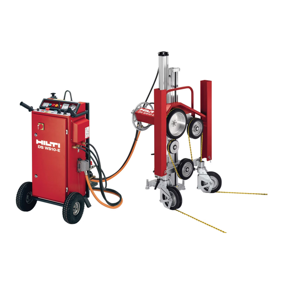
ORIGINAL OPERATING INSTRUCTIONS DS WS10 / DS WS10-E diamond wire saw system Contents It is essential that the operating instructions are read 1. General information before the machine is operated for the first time. Always keep these operating instructions together 2. - Page 3 Parts and equipment DS WS10 hydraulic wire saw ³ Compact wire saw with hydraulic drive · Air compressor with control panel » Air hoses (2×7 m, 1×1 m) ¿ Positioning template ´ Water hoses (2×10 m) ² Water nozzle, flexible ¶...
-
Page 4: General Information
Make a note of this data in your operating instructions and always Wear eye Wear a hard hat. Wear protective Wear safety refer to it when making an enquiry to your Hilti repre- protection. gloves. footwear. sentative or service department. Type:... -
Page 5: Description
2. Description Description 2.1 Use of the equipment as directed 2.2 Components 2.3 Operating controls 2.4 Drive principle 2.5 Saw advance and wire storage 2.6 Wire guidance Printed: 08.07.2013 | Doc-Nr: PUB / 5069736 / 000 / 01... -
Page 6: Description
Guide rail and advance unit process, may produce toxic, hazardous or explosive Pivoting pulley crossbar dust or vapors. Hydraulic drive unit (DS WS10) or electric drive unit I Do not cut easily combustible aluminum or magne- (DS WS10-E) sium alloys. -
Page 7: Operating Controls
2. Description Guide rail and advance unit Operating controls and parts Internal taper Eccentric pin Positioning template Carriage locking mechanism Grip Manual advance mechanism Edge indicating line of cut Piston rod securing clamp Wire entry point Return lock Pivotable drilling point indicator Compressed air connection Optimum anchor position Drive unit interface and locking mechanism... - Page 8 2. Description Pivoting pulley crossbar DS WS10-E electric drive unit Attachment point and clamp Mounting interface Pivoting pulley locking lever Power cable Wire storage pulley Drive pulley Guard mounting hole Return pulley Hollow axles Carrying / holding bar Guard Guard guides Traction pulley Cooling water connection –...
- Page 9 2. Description DS WS10 water connection DS WS10 pneumatic system control unit Coupling (water outlet from hydraulic unit) Advance direction control valve Flow regulation and shut-off valve Regulator for advance pressure adjustment Water hose connection (cooling water nozzles) (wire tension)
- Page 10 2. Description DS WS10-E control unit Electric supply connection 400 V~ / 32 A or 200 V~ Transport and carrying handles / 63 A Lifting point for lifting by crane 230 V electric supply socket (not fitted to 200 V~...
-
Page 11: Drive Principle
2. Description Drive principle The sawing wire is passed around the object to be cut, over guide pulleys and the drive pulley before the ends of the wire are joined to form an endless loop. The wire loop is set in motion by rotation of the drive pulley and pulled through the object to be cut by the linear advance movement of the drive unit. - Page 12 Printed: 08.07.2013 | Doc-Nr: PUB / 5069736 / 000 / 01...
-
Page 13: Accessories
3.4 Release pulley (optional) 3.5 Wire guard (optional) 3.6 Accessories for setting up and operating the wire saw and wire guides 3.7 Accessories and wearing parts for Hilti wire saw systems Printed: 08.07.2013 | Doc-Nr: PUB / 5069736 / 000 / 01... - Page 14 3. Accessories I Observe the wire and wire connector manufacturer’s Hilti sawing wires and accessories instructions when connecting sawing wires and, as far as possible, use only one wire connector in each Safety precautions and instructions for use complete wire loop.
- Page 15 371 991 per/m 384 539 376 635 376 634 377 830 377 781 377 782 * with factory-fitted flexible connectors Accessories for connecting Hilti diamond wires Designation Package Ordering designation Item no. contents Crimping pliers DS-WSTHY 235845 For crimping connectors / repair sleeves...
- Page 16 3. Accessories Wire storage extension (optional) Release pulley The wire storage extension can be used to increase wire The release pulley is used to reduce the length of wire storage capacity from 250 cm to 500 cm. in contact or to increase the radius of the arc followed by the wire (avoiding a tight radius) at the rear of the object to be cut.
- Page 17 Water supply GK seal 356701 Water seal for 356700 Steel wedge 41910 Securing concrete blocks Accessories and wearing parts for Hilti wire saw systems Ordering designation Quantity Item no. M12L clamping spindle, long 251831 Fastening HKD-D M12×50 flush anchor *...
- Page 18 Printed: 08.07.2013 | Doc-Nr: PUB / 5069736 / 000 / 01...
-
Page 19: Technical Data
4.1 Technical data for the DS WS10 hydraulic drive 4.2 Technical data for the DS WS10-E control unit 4.3 Dimensions and weights 4.4 Technical data for the DS WS 10 and DS WS10-E 4.5 Compressed air supply 4.6 Wire storage capacity and length requirements 4.7 Type plates... -
Page 20: Technical Data
The DS-WS 10 compact wire saw is designed for oper- The operator will notice when the flow rate limiting device ation with the Hilti D-LP 15 and D-LP 32 or D-LP 30 is activated as the drive unit then no longer runs smooth- hydraulic power units. -
Page 21: Dimensions And Weights
4. Technical data Dimensions and weights Dimensions of drive and wire storage unit Dimensions of DS WS10 compressor with control unit Weight of DS WS10-E: 81.2 kg Weight: 20.1 kg Weight of DS WS10: 69.5 kg Dimensions of DS WS10-E control unit... -
Page 22: Technical Data For The Ds Ws 10 And Ds Ws10-E
10 m Power cable (DS WS10-E): Hydraulic hoses (DS WS10)*: 10 m * not supplied with the wire saw max. 610 Technical data for the DS WS10 and DS WS10-E drive units DS WS10 DS WS10-E DS WS10-E hydraulic 3x400 V... -
Page 23: Compressed Air Supply
4. Technical data Compressed air supply The compressor for the air supply is supplied as part of the wire saw system (but not with the 3 x 200V version). Please observe the operating instructions enclosed with Pressure min. / max. 6 / 8 bar Flow rate 205 l/min... -
Page 24: Type Plates
Typical A-weighted sound power level DS WS10 hydraulic drive unit as per ISO 3744: DS WS10 DS WS10-E 103.7 dB(A) Hilti = trademark of Hilti Corporation, Schaan, LI Made in Austria Serial number 0001000 DS WS10 with D-LP15 102.1 dB(A) Drive wheel ø... -
Page 25: Safety Instructions
5. Safety instructions Safety instructions 5.1 Proper organization of the work area 5.2 Safety measures at the danger area 5.3 General safety measures 5.4 Electrical safety 5.5 Requirements to be met by users 5.6 Safety during operation 5.7 Safety instructions for transporting the wire saw Printed: 08.07.2013 | Doc-Nr: PUB / 5069736 / 000 / 01... - Page 26 5. Safety instructions l) Keep children away. Keep other persons away from the working area. WARNING m) Do not allow other persons to touch the machine Failure to observe the instructions listed below may or the extension cord. lead to potentially fatal injury and serious damage to n) Avoid unfavorable body positions.
- Page 27 Hilti specialist on safe operating pro- cedures. All warnings and instructions must be observed. b) Use the right machine for the job. Do not use the machine for purposes for which it was not intended.
- Page 28 Damaged or faulty switches must be replaced at a ply when it is not in use (e.g. during breaks between Hilti service center. Do not use the machine if it cannot working), before making adjustments, before carrying be switched on and off correctly.
- Page 29 Hilti for wood dust and/or mineral ed field of use. Do not work with extension cables when dust together with this tool. Ensure that the work- they are rolled up.
- Page 30 No modifications may be made to the saw system equip- ment. Alteration of the factory-set frequency convert- er parameters (DS WS10-E) is not permissible. Safety instructions for transporting the wire Avoid lifting and carrying heavy objects. Use suitable lift- ing equipment and means of transport and share heavy loads between several people.
-
Page 31: Preparations At The Workplace
6.3 Examples of applications 6.4 Determining the necessary wire capacity and wire length 6.5 Clarifying the situation and securing the workplace 6.6 Electric power supply / fuse rating – DS WS10-E 6.7 DS WS10-E wiring diagram 6.8 Extension cables / conductor cross sections 6.9 Cooling water supply... - Page 32 Please consult a Hilti wire sawing specialist before using other wire guid- ance configurations. Planning wire guidance and the cutting sequence Horizontal or vertical cut, 20–40 cm cutting length...
- Page 33 6. Preparations at the workplace Horizontal or vertical cut, 70–200 cm cutting length Horizontal or vertical, 50–200 cm cutting length Flush cutting, 50 to approx. 100 cm length Horizontal or vertical, transverse cutting technique Beam or column, 30 to approx. 100 cm cutting length Determining the necessary wire capacity and wire length...
- Page 34 63 A Ground fault The machine’s automatic cut-out will be activated in the circuit breaker: 30 mA (type A) 30 mA (type A) event of inadequate cooling (DS WS10-E). Printed: 08.07.2013 | Doc-Nr: PUB / 5069736 / 000 / 01...
-
Page 35: Preparations At The Workplace
6. Preparations at the workplace Use only clean cooling water. Where pressure in the water supply line is low, a non- return valve should be fitted in order to prevent dirty water finding its way into the water supply. Printed: 08.07.2013 | Doc-Nr: PUB / 5069736 / 000 / 01... - Page 36 Printed: 08.07.2013 | Doc-Nr: PUB / 5069736 / 000 / 01...
-
Page 37: Setting Up The Saw System
7.11 Connecting the air hoses to the control unit 7.12 Connecting the water supply 7.13 Connecting the hydraulic hoses (DS WS10) 7.14 Connecting the power cable to the control unit (DS WS10-E) Printed: 08.07.2013 | Doc-Nr: PUB / 5069736 / 000 / 01... -
Page 38: Setting Up The Saw System
Under certain conditions it may be necessary to use an alternative fastening method. Please contact Hilti Technical Service if you have any questions about secure fastening. Your Hilti representative will be pleased to provide advice in case of questions concerning fastening security on Printed: 08.07.2013 | Doc-Nr: PUB / 5069736 / 000 / 01... -
Page 39: Attaching The Guide Rail Unit
Procedure a) Use the template to mark the position of the anchor hole. b) Drill the hole, clean the hole, insert the Hilti HKD-D anchor and expand it. c) Screw in the clamping spindle as far as it will go. -
Page 40: Fitting The End Stop
7. Setting up the saw system Fitting the end stop Mounting the drive unit Fitting the end stop. Pull out the carriage clamping pins. CAUTION Do not, under any circumstances, operate the saw with- out a correctly and securely fitted end stop. Fitting the pulley crossbar Guide the clamping piece into the slot in the carriage. -
Page 41: Connecting The Air Hose To The Pneumatic Cylinder
7. Setting up the saw system Connecting the air hose to the pneumatic cylinder Feed the wire through the hollow axles of the pulley stands (if used) and subsequently through the hollow axles on the pulley crossbar on the compact wire saw. To ensure that the sawing wire wears evenly and stays round, we recommend that the wire is twisted in a coun- terclockwise direction (approx. -
Page 42: Fitting The Guards
7. Setting up the saw system 7.10 Fitting the guards Piston rod securing lever Release the return lock , slide the piston rod all the Bring the guard into position. way in and then lock the piston rod and return lock in position. -
Page 43: Connecting The Air Hoses To The Control Unit
(DS WS10). Connect the cooling nozzle water hoses to the 3-way connector (DS WS10). Fit the T-piece connector to the drive unit (DS WS10- Connect the compressed air hoses to the compressor and to the control unit (DS WS10-E). -
Page 44: Connecting The Hydraulic Hoses (Ds Ws10)
(DS WS10) (DS WS10-E) Connect the power cable and secure the plug (DS WS10-E). Connect the hydraulic hoses to the drive unit (DS WS10). Connect the hydraulic hoses to the valve block / hydraulic unit (D-LP15 / D-RC22 or D-LP32). CAUTION... -
Page 45: Operation And The Sawing Procedure
8. Operation and the sawing procedure Operation 8.1 Checks before beginning sawing and the sawing procedure 8.2 Setting the starting cutting pressure 8.3 The starting procedure 8.4 Checks while sawing is in progress 8.5 Readjusting saw advance at the end of the stroke 8.6 Steps before and after ending the sawing operation Printed: 08.07.2013 | Doc-Nr: PUB / 5069736 / 000 / 01... - Page 46 I Is the advance cylinder stroke length adequate? I Have the electric cables, water hoses, air hoses and, where applicable, the hydraulic hoses (DS WS10) been laid in a safe position, connected correctly and the con- nections secured?
- Page 47 I The water valves are open and cooling water is being fed directly to the cutting face. Switch on the main DS WS10-E drive unit and allow the wire to start running. I Set the advance pressure to approx. 1 to 2 bar at the control unit by means of the control knob (pull out to release).
- Page 48 (middle) position. I Take care to ensure that the hydraulic pressure (DS WS10) remains within the 80 to 120 bar range or, respectively, the electric current drawn (DS WS10-E) remains just below the red area on the gauge. If the...
-
Page 49: Operation And The Sawing Procedure
8. Operation and the sawing procedure Steps before and after ending the sawing operation CAUTION Always check that the advance cylinder is not under I Before cutting right through, take care to ensure that pressure before releasing the advance movement lock- the wire, when released from the kerf, can be caught by ing lever. - Page 50 Printed: 08.07.2013 | Doc-Nr: PUB / 5069736 / 000 / 01...
-
Page 51: Cleaning, Maintenance And Repair
Cleaning, maintenance and repair 9.1 Cleaning 9.2 Maintenance 9.3 Electrical circuit diagram for DS WS10-E 3x200 V control unit 9.4 Electrical circuit diagram for DS WS10-E 3x200 V control unit (control circuit) 9.5 Electrical circuit diagram for DS WS10-E 3x400 V control unit 9.6 Electrical circuit diagram for DS WS10-E 3x400 V control unit... -
Page 52: Cleaning, Maintenance And Repair
Clean all parts of the system, except electrically powered units such as the compressor and the hydraulic unit (DS WS10) or control unit (DS WS10-E), with a medium- hard brush and plenty of water right away at the end of each working day. -
Page 53: Electrical Circuit Diagram For Ds Ws10-E 3X200 V Control Unit
9. Cleaning, maintenance and repair Electrical circuit diagram for DS WS10-E 3x200 V control unit Printed: 08.07.2013 | Doc-Nr: PUB / 5069736 / 000 / 01... -
Page 54: Electrical Circuit Diagram For Ds Ws10-E 3X200 V Control Unit (Control Circuit)
9. Cleaning, maintenance and repair Electrical circuit diagram for DS WS10-E 3x200 V control unit (control circuit) Printed: 08.07.2013 | Doc-Nr: PUB / 5069736 / 000 / 01... -
Page 55: Electrical Circuit Diagram For Ds Ws10-E 3X400 V Control Unit
9. Cleaning, maintenance and repair Electrical circuit diagram for DS WS10-E 3x400 V control unit Printed: 08.07.2013 | Doc-Nr: PUB / 5069736 / 000 / 01... -
Page 56: Electrical Circuit Diagram For Ds Ws10-E 3X400 V Control Unit (Control Circuit)
9. Cleaning, maintenance and repair Electrical circuit diagram for DS WS10-E 3x400 V control unit (control circuit) Printed: 08.07.2013 | Doc-Nr: PUB / 5069736 / 000 / 01... -
Page 57: Pneumatic Circuit Diagram For The Wire Saw Drive Unit
9. Cleaning, maintenance and repair Pneumatic circuit diagram for DS WS10 / DS WS10-E Printed: 08.07.2013 | Doc-Nr: PUB / 5069736 / 000 / 01... - Page 58 Printed: 08.07.2013 | Doc-Nr: PUB / 5069736 / 000 / 01...
-
Page 59: Troubleshooting
(DS WS10-E) 10.17 No power at the 230V power outlet (DS WS10-E) 10.18 Current input is too high when idling and sawing (DS WS10-E) 63 10.19 The service indicator lights and the drive unit may be inoperative (DS WS10-E) 10.20 The ground fault circuit interrupter has been tripped... -
Page 60: Troubleshooting
– Reduce tension by reducing pressure in the system. The length of wire in contact / cutting length is too long The working hydraulic pressure (DS WS10) or elec- – Divide the cut up into several shorter lengths. tric current input (DS WS10-E) is too low –... -
Page 61: The Sawing Wire Wears Unevenly / One-Sided
10. Troubleshooting Too little cooling / flushing water (dust is created) The sawing wire was not pushed far enough into the – Direct the flow of water exactly toward the wire and connector in to the kerf. – Push the wire into the connector as far as it will go. –... -
Page 62: The Air Compressor Doesn't Start
10.14 The machine doesn’t start, the green “ready” tioning and renew the filters if necessary. indicator lamp doesn’t light (DS WS10-E) NOTE: To reset the power converter, wait approx. 30 sec- onds and then press the reset button. The cable is not under power –... -
Page 63: Current Input Is Too High When Idling And Sawing (Ds Ws10-E)
10.18 Current input is too high when idling and sawing (DS WS10-E) – The saw has been in operation for at least 200 hours. The drive unit and control panel must be returned for servicing as soon as possible in order to prevent dam- age. -
Page 64: Disposal
The materials must be correctly separated before they can be recycled. In many countries, Hilti has already made arrangements for taking back old machines and appli- ances for recycling. Ask Hilti customer service or your Hilti representative for further information. -
Page 65: Manufacturer's Warranty
12. Manufacturer’s warranty Hilti warrants that the tool supplied is free of defects in material and workmanship. This warranty is valid so long as the tool is operated and handled correctly, cleaned and serviced properly and in accordance with the Hilti Operating Instructions, and the technical system is main- tained. -
Page 66: Ec Declaration Of Conformity (Original)
2006/42/EC, 2004/108/EC, EN 60204-1, EN ISO 12100, 2011/65/EU This equipment (DS WS10-E) complies with the applicable standard provided that the short-circuit power S at the interface point between the user’s supply and the public supply network is greater than or equal to 1.3 MVA. - Page 67 Printed: 08.07.2013 | Doc-Nr: PUB / 5069736 / 000 / 01...
- Page 68 LI-9494 Schaan Tel.: +423 / 234 21 11 Fax: +423 / 234 29 65 www.hilti.com Hilti = registered trademark of Hilti Corp., Schaan W 3591 I 1212 I 1-en I 1 Printed in Liechtenstein © 2012 247002 / Right of technical and programme changes reserved S. E. & O.
Need help?
Do you have a question about the DS WS10 and is the answer not in the manual?
Questions and answers