Bluetti EP900 - Energy Storage System Manual
- User manual (86 pages) ,
- Installation manual (60 pages) ,
- Troubleshooting manual (16 pages)
Advertisement
- 1 Introduction
- 2 Working mode
- 3 EP900 Inverter
- 4 B500 Battery
- 5 System Check
- 6 Dispose of EP900 Energy Storage System
- 7 Troubleshooting
- 8 Specifications
- 9 SAFETY
- 10 Documents / Resources
Introduction
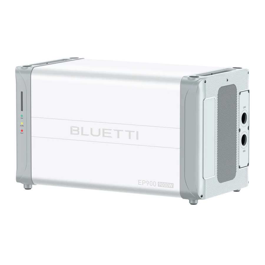
BLUETTI EP900 is a modular Energy Storage System (ESS) featuring 9000W output, 9000W input and a maximum capacity of 39kWh. With an intelligent Battery Management System (BMS) and reliable Lithium Iron Phosphate(LFP) battery pack, EP900 always gives its optimal performance regardless of the cold or hot weather.
Whether you're trying to get rid of high electric bills, are tired of fluctuating power supply that happens now and then, or getting ready for clean energy solutions, the BLUETTI EP900 ESS is right for you.

Figure EP900 Energy storage system
| Item | Description | Note |
| EP900 Inverter | An energy storage photovoltaic grid-connected inverter to handle photovoltaic input, grid-connected charging, and discharging. | For details, please refer to "EP900 Inverter". |
| B500 Battery | LiFePO4 battery pack to power the EP900 system. | For details, please refer to "B500 Battery". |
| IoT Controller | Monitor and control the EP900 system. | For details, please refer to "IoT Controller". |
| Grid Communication Module | Used for the power interconnection between EP900 ESS and the power grid through WiFi, to optimize the power consumption and enjoy the subsidy policies. | Interconnect with IEEE 2030.5 compliant North American Grid servers for plug-and-play, remote dispatch and data monitoring functionality. |
| BLUETTI APP | Near-end communication (Bluetooth) or remote communication (WIFI) with EP900 inverter | For details, please refer to BLUETTI APP instructions. |
| CT (Current Transformers) | Assist in intelligent operation management. | / |
| Fast breaker | Quickly de-energize a rooftop solar panel system. | / |
| Safety switch | Used for the security protection of the grid-connected line. | / |
Working mode
 The introduction describes the general behavior of EP900 energy storage system, and the system operating mode can be adjusted on the APP of this product.
EP900 ESS has four operating modes to cope with different energy plans. Please select the appropriate mode based on your home power supply configuration.
Mode 1
If there is already a grid-connected PV system, combine it with the EP900 ESS by means of AC coupling. The PV power is first used to power the load and then to charge the batteries, and any excess PV power can be fed back to the grid.

Mode 2
When there is no PV system, the load is powered by the backup battery, and then by the grid when the battery is low.

Mode 3
If the grid is disconnected, the PV and backup batteries work together to provide power to the load.

Mode 4
Battery can be charged by grid, the charging time and power can be set flexible in APP.

EP900 Inverter
EP900 inverter is an energy storage photovoltaic grid-connected inverter that can handle photovoltaic input, grid-connected charging, and discharging. It is an important part of the energy storage system.
Features
Take advantage of solar energy: Triple MPPT charge controllers to maximize solar input, while store solar energy in LiFePO4 batteries. It also works with the grid-connected PV system.
Smart energy storage solution: Intelligent user application mode, which can automatically control the flow of system charging and discharging power or according the user demand to adjust the energy actively.
Uninterruptible power supply (UPS): It takes less than 10ms to switch from off on-grid connection to off grid.
Battery expansion: The ESS supports 2-4 battery packs (B500) to expand the total capacity.
App control & monitor: With WiFi or Bluetooth connection, you can check the system operation anytime and anywhere.
IP65 water-resistant: The ESS is not subject to dust and water splashes from all directions, making it suitable for indoor and outdoor use. If you place the system outside the house, use a cabinet to protect it from direct sunlight.
Supported Grid Form
The EP900 grid-connected inverter supports low-voltage power grid. The grid form is L1/L2/N, as shown in the following figure.

240/120 split phase

240 delta
Overview
Appearance
Left

Right

Dimensions
Front

Right

Interface
Left

Right

| No. | Port name | No. | Port name |
| 1 | PV input 1 | 9 | Bleed valve |
| 2 | PV input 2 | 10 | COM port |
| 3 | DC switch | 11 | CT port |
| 4 | BAT- terminal | 12 | DRMs port |
| 5 | LED indicator | 13 | USB port |
| 6 | IoT signal port (Link Port 1) | 14 | Load port |
| 7 | Battery signal port (Link Port 2) | 15 | Grid port |
| 8 | BAT+ terminal | 16 | Grounding port |
LED Indicator

| Situation | Run | Alarm | Fault |
| No alarm and fault | ON | / | / |
| Alarm | ON | ON | / |
| Fault | / | / | ON |
| Alarm and fault | / | ON | ON |
Buzzer Alarm
The buzzer beeps 10 times when a fault occurs. Each time lasts for 5 seconds with an interval of 1 second. The buzzer sound can be turned off on your phone.
Table Fault Code
| Fault Code | Content |
| 5. | BUS overvoltage |
| 6. | BUS2 overvoltage |
| 7. | Battery overvoltage |
| 8. | Inverter overcurrent |
| 9. | Inverter2 overcurrent |
| 10. | LLC1 current overcurrent input |
| 11. | LLC2 current overcurrent input |
| 26. | PV fault |
| 34. | Overcurrent input |
Routine maintenance
To ensure the safe and smooth operation of the EP900 ESS, follow the checklist below for regular routine maintenance.
- Check fans and heat sinks for dust and other debris that may also accumulate on other components within the system, reducing power efficiency and increasing wear and tear.
- Check that fans are running properly, without any noise or other abnormalities.
- Check that all cables are secured. Please use a torque wrench to tighten the AC and DC cable connections annually.
B500 Battery
Introduction
The B500 battery energy storage system is designed for residential and light commercial use. Single B500 battery pack has a capacity of 4.96kWh. BLUETTI EP900 system supports 4 *B500 units for a whopping 19.84kWh, enough to power a house for several days.
The B500 comes with a reliable battery management system (BMS) with a multi-stage architecture that provides real-time detection of the battery pack's voltage, current and temperature, protecting the system from overvoltage, undervoltage, overcurrent, overtemperature and undertemperature. At the same time, the redundancy design provides unprecedented safety and stability for the B500 battery energy storage system.
Overview
Appearance
Left

Right

Interface
Left

Right

| No. | Name | No. | Name |
| 1 | BAT- terminal 1 | 8 | Bleed valve 1 |
| 2 | Pack link-in | 9 | BAT+ terminal 2 |
| 3 | Pack link-out | 10 | Power button |
| 4 | BAT- terminal 2 | 11 | Grounding port 1 |
| 5 | Main switch | 12 | Grounding port 2 |
| 6 | BAT+ terminal 1 | 13 | Bleed valve 2 |
| 7 | Inverter signal port (TO Pcs) |
Dimensions
Table (Unit: in/mm)
Front

Right

Indicator Description
| Light | Meaning | Note |
| OFF | B500 is not started. | Can operate the circuit breaker. |
| ON | B500 is running. | Can not operate the circuit breaker. |
| Flash at 0.5Hz | B500 is shutting down. | Can not operate the circuit breaker. |
| Flash at 1Hz | B500 is not running. | If all indicators are flashing, the battery module is temporarily unavailable and is restoring, please wait patiently. If it lasts for more than 1 hour, please contact an authorized dealer or our company. If a single indicator flashes, the B500 is in a fault condition. Please contact an authorized dealer or our company. |
Maintenance
- If some of the indicators are off for the battery packs connected in parallel, please contact us or the authorized dealer.
- If you find the B500 battery pack is in a faulty state, please contact us or the authorized dealer.
- If you find the B500 battery pack is temporarily unable to work and is restoring, please wait patiently. If it lasts for more than 1 hour, contact the authorized dealer or our company immediately.
- If the circuit breaker trips, do not operate B500 yourself. Please contact an dealer or our company for further assistance.
- Do not switch off the circuit breaker when B500 battery pack is running, as this may result in abnormal operation of the B500.
- Do not remove the metal shell of B500, as this may cause electric shock and explosion.
System Check
Preliminary Check
Check the followings before first use.
- Confirm that all components of the system are installed according to specific requirements.
- Make sure the PV+/PV- and BAT+ and BAT- cables are connected with correct polarity and proper voltage.
- Switch off all AC and DC circuit breakers.
- Circuit breakers should be selected according to the requirements of this manual and local regulations.
- Make sure grid and load cables are held firmly in place.
- All safety signs and warning labels shall be firmly attached and clearly visible when needed.
Power On
Step1: Switch on the DC circuit breakers on EP900.
Step2: Switch on the DC circuit breakers on B500 battery packs. Press and hold the power button on any B500 till the indicator on the button light up green.
Step3: Wait for about 40 seconds till the inverter indicator keeps steady green.
Step4: Switch on the AC circuit breakers connected to the EP900 grid port.
Step5: Power on the system via BLUETTI app. For details, please refer to BLUETTI App Instructions.
Step6: Check the output voltage of BACKUP battery.
Step7: Switch on the AC circuit breakers connected to the EP900 load port.
Step8: Check the EP900 system status through the app.
Power Off
Step1: Turn off the AC power on BLUETTI App.
Step2: Switch off the AC circuit breakers which are connected to EP900 grid ports and load ports.
Step3: Switch off EP900 PV breaker.
Step4: Press the power button on any B500 till the indicator on the button flashes green.
Step5: The indicator continues to flash.
Step6: When the indicator is off, B500 battery packs turn off.
Step7: Switch off main switches for all B500 and the system powers off.

There is still residual voltage after the equipment is powered off, which may cause electric shock or burns. Please wait at least 30 minutes before operating the system.
Dispose of EP900 Energy Storage System
Remove the EP900 Inverter
When the inverter is no longer in use, it must be disposed of properly.
- Power off the system.
- Disconnect all electrical connections to the inverter, such as signal cable, DC input cable, power cable, AC input cable, grounding cable, etc.
- Remove the inverter and related parts.
Recycle the EP900 Inverter and B500 battery pack
When the inverter or battery pack reaches the end of its lifespan, it must be safely and carefully disposed of by the provisions of local laws and regulations.
Please contact our company for further assistance if the battery pack is
- Leaked or damaged.
- Out of warranty or severely degraded in performance.
- To be replaced or not intended for further use.
Troubleshooting
Table 7-1
| No. | Error Description | Solution |
| 1. | BUS Overvoltage | Turn off the inverter and wait 30 minutes to restart it. If the symptom persists, please contact the BLUETTI support team. |
| 2. | BUS2 Overvoltage | |
| 3. | BUS Undervoltage | |
| 4. | BUS2 Undervoltage | |
| 5. | Hardware BUS overvoltage | |
| 6. | Hardware BUS2 overvoltage | |
| 7. | Hardware Battery Overvoltage | |
| 8. | Hardware Inverter Overcurrent | |
| 9. | Hardware Inverter2 Overcurrent | |
| 10. | Hardware LLC Input Overcurrent | |
| 11. | Hardware LLC2 Input Overcurrent | |
| 12. | ||
| 13. | Auxiliary Power Undervoltage | |
| 14. | DC Component Exception | |
| 15. | Relay Failure | |
| 16. | PV Connection Error | |
| 17. | PV1 Overcurrent | Turn off the inverter and wait 30 minutes to restart it. If the symptom persists, please contact the BLUETTI support team. |
| 18. | PV2 Overcurrent | |
| 19. | Reserved | |
| 20. | PV1 Voltage High | Check if the total voltage of solar panels exceeds the limit. Reduce the number of solar panels, and the inverter resumes operation after calibration. |
| 21. | PV2 Voltage High | |
| 22. | PV3 Voltage High | |
| 23. | PV1 ISO Failure | Check the insulation resistor between solar array and grounding for a short circuit. |
| 24.-26. | ||
| 27. | PV1 ISO Failure | |
| 28.-30. | ||
| 31. | Phase Sequence Error | Check if the grid connection meets installation requirements. |
| 32. | Fan Failure | Check if the inverter fan operates well. |
| 33. | Zero Drift Anomaly | Turn off the inverter and wait 30 minutes to restart it. If the symptom persists, please contact the BLUETTI support team. |
| 34. | Hardware Input Overcurrent | |
| 35. | DC Input Voltage Low | Check if the DC voltage is too low. |
| 36. | DC Input Voltage High | Check if the DC voltage is inconsistent with the battery specifications. |
| 37.-39. | ||
| 40. | Inverter Overload | Check if the inverter is overloaded. |
| 41. | L2 Inverter Overload | |
| 42. | ||
| 43. | L1 Inverter Output Failure | |
| 44. | L2 Inverter Output Failure | |
| 45. | ||
| 46. | ||
| 47. | Communication Failure | Turn off the inverter and wait 30 minutes to restart it. If the symptom persists, please contact the BLUETTI support team. |
| 48. | ||
| 49. | DSP Communication Interrupted | Turn off the inverter and wait 30 minutes to restart it. If the symptom persists, please contact the BLUETTI support team. |
| 50. | BMS Communication Interrupted | Check that the external communication terminals are connected correctly and restart the device. If the symptom persists, please contact the BLUETTI support team. |
| 51. | IOT Communication Interrupted | |
| 52. | Zero Drift Anomaly-ARM | Turn off the inverter and wait 30 minutes to restart it. If the symptom persists, please contact the BLUETTI support team. |
| 53. | RTC Read and Write Anomaly | |
| 54. | Reserved | |
| 55. | Operating Ambient Temperature Anomaly | Please make sure use the system within specific temperature range. If the symptom persists, please contact the BLUETTI support team. |
| 56. | Temperature 1 Anomaly | |
| 57. | Temperature 2 Anomaly | |
| 58. | Temperature 3 Anomaly | |
| 59. | Temperature 4 Anomaly | |
| 60. | BMS Charge Protection | Check the details on BLUETTI app. |
| 61. | BMS Discharge Protection | |
| 62. | BMS System Failure | |
| 63.-96. | Reserved | |
| 97. | Grid Voltage High | If it occurs occasionally, the grid may go through abnormal working conditions. The inverter recovers after the grid resumes. If it occurs many times, check if the grid voltage and frequency support the inverter input specifications. Check the inverter AC circuit breaker and connections. If the voltage and frequency are beyond the range, please contact the BLUETTI support team. |
| 98. | Grid Voltage Low | |
| 99. | Grid Over Frequency | |
| 100. | Grid Low Frequency | |
| 101. | Reserved | |
| 102. | Grid Loss | |
| 103. | PV1 Voltage Low | Check the PV setup for proper working condition. Solar panels may get a low voltage under improper working conditions. |
| 104. | PV2 Voltage Low | |
| 105. | Reserved | |
| 106. | ||
| 107. | DSP_Debug CAN Communication Failure | |
| 108. | DSP_Debug RS485 Communication Failure | |
| 109.-128. | Reserved | |
| 129. | EEPROM Read and Write Anomaly | Please reconfigure the settings on BLUETTI app. If the symptom persists, please contact the BLUETTI support team. |
| 130.-133. | Reserved | |
| 131. | USB Format Error | The USB is formatted as FAT32 with no more than 32G in size. Check if the upgrade files exist or expire. Please download the latest upgrade files. |
| 132. | USB Upgrade Failure | Turn on the inverter again. If the symptom persists, please contact the BLUETTI support team. |
| 133. | Arcing Detection Anomaly | |
| 134. | USB Communication Anomaly | |
| 135. | USB No Upgrade File | |
| 136. | CT Connection Direction Error | Check that the CT connection direction and phase sequence are correct. If the symptom persists, please contact the BLUETTI support team. |
| 140. | Meter communication Failure | Check whether the meter is powered and whether the communication cable between the meter and the EP900 energy storage system is connected normally. If the problem persists, please contact technical support. |
| 141. | Arc pulling module self-test failure | Please restart the machine. If the problem persists, please contact BLUETTI technical support. |
| 142. | Arc pulling module communication failure | Please restart the machine. If the problem persists, please contact BLUETTI technical support. |
Specifications
Table EP900 Inverter
AC (Grid-tied)
| Item | Description | Remarks |
| Rated Output Power (240V) | 9000W | |
| Wiring mode | L1/L2/N/G | |
| Rated Voltage | 120VAC/240VAC | |
| Voltage Range | 110V~126V/220V~252V | |
| Rated Output Current | 37.5A ×2 | |
| Input Frequency | 60Hz | |
| Frequency Range | 55Hz~65Hz | |
| Maximum InputApparent Power | 13500VA | Bypass + Charge |
| Maximum Input Current | 58A | Bypass + Charge |
| Power Factor (PF) | 1.0 | 0.9 leading - 0.9 lagging |
| Current Total Harmonic Distortion (THD) | ||
| On and Off-Grid Switching Time | ||
| Round-trip Efficiency | >85%(AC/AC) | Grid-Battery-AC Load |
| Protection | Anti-islanding protection Output overcurrent protection Short-circuit protection\ Over-temperature derating Over-temperature shutdown | PV is on the battery side, with no residual current detection |
AC (Off-Grid)
| Item | Description | Remarks | ||
| Rated Output Power | 9000W | |||
| Output Voltage | 120V/240V | |||
| Output Current | 37.5A ×2 | |||
| Peak Current Ratio | 2.4:1 | |||
| Output Frequency | 60Hz | |||
| Inversion Efficiency | 94.4% Max. | |||
| Output Voltage THD | <3% | Purely resistive load | ||
| Overload | 100%~110%, 10min 110%~150%,10s >150%, 100ms | |||
| Protection | Output overcurrent protection Output short-circuit protection Over temperature protection | |||
PV Input
| Item | Description | Remarks | ||
| Maximum Input Power | 9000W | |||
| MPPT Channel | 2 | 3000W + 6000W | ||
| Array In Series | 1/2 | 3000W + 6000W | ||
| Maximum Input Voltage | 550V | |||
| MPPT Voltage Range/Rated | 150V~500V/360V | |||
| Single MPPT Maximum Input Current | 12.5A/25A | |||
| Single MPPT Maximum Short-circuit Current | 15A/30A | |||
| MPPT Efficiency | 99.9% | |||
| PV Inversion Efficiency | 97.0% Max. | |||
| Protection | Reverse polarity protection Insulation resistance detection Arcing detection | |||
General
| Item | Description |
| Relative Humidity | 5%-95% |
| Static Power | 23W |
| Standby Power | 75W |
| Working Temperature | -4~122oF |
| Noise | ≤50dB (A) |
| Cooling | Forced air cooling |
| Protection Grade | IP65 |
| Working Altitude | |
| Dimensions (L*W*H) | 636mm×324mm×368mm |
| Net Weight | 44kg |
| Communication | USB/WiFi/Bluetooth |
| Warranty | 10 Years |
Compliance
| Item | Description |
| System | UL9540 |
| Inverter | UL1741, UL1741 SA |
| Grid Connections | UL1741 SA, SB, IEEE1547, IEEE1547.1, CSA22.2, No.107.1, UL1998, California Rule 21 |
| Emissions | FCC Part 15 Class B |
| Surge Protection | IEEE C62.41 Class B |
| Others | NEMA 4X, CEC Efficiency, California Proposition65 |
Table 8-2 B500
Battery
| Item | Description | Remarks |
| Battery Type | LiFePO4 | Lithium iron phosphate cells |
| Battery Voltage | 99.2V | 3.2V×31 |
| Rated Capacity | 4960Wh | Charging: 0.5oC/3.6V/0.05oC Discharging: 0.5oC/2.5V (25oC) |
| Usable Capacity | 4464Wh | 90% DOD Charging: 0.5oC Discharging: 0.5oC (25oC) |
| Cell Overvoltage Protection | 3.7V | |
| Cell Undervoltage Protection | 2.5V | |
| Maximum Input Voltage | 108.5V | 3.5V×31 |
| Minimum Output Voltage | 86.8V | 2.8V×31 |
| Maximum Input Current | 25A | The continuous input current is affected by temperature and SoC. |
| Maximum Input Current | 50A | The continuous output current is affected by temperature and SoC. |
| Short-circuit Protection | Yes | |
| Discharging Over Temperature Protection | 141.8oF | |
| Discharging Over Temperature Recovery | 127.4oF | |
| Discharging Under Temperature Protection | -7.6oF | |
| Discharging Under Temperature Recovery | -0.4oF | |
| Charging Over Temperature Protection | 132.8oF | |
| Charging Over Temperature Recovery | 116.6oF | |
| Charging Under Temperature Protection | 30.2oF | |
| Charging Under Temperature Recovery | 33.8oF | |
| Charging Strategy | BMS Orders | CC/CV |
General
| Item | Description | Remarks | |||
| Noise | <25dB | No fan | |||
| Number of Battery in Parallel | Up to 4 batteries supported | System capacity will be halved at 2 packs. | |||
| Operating Temperature | Charging | 32oF~104oF | |||
| Charging | -4oF~104oF | Inverter connects to the grid. | |||
| Discharging | -4oF~104oF | ||||
| Storage Temperature | -4oF~104oF/At least one charge cycle per month. 32oF~95oF/At least one charge cycle every six months. | ||||
| Working Humidity | 5%-95% | ||||
| Working Altitude | |||||
| Cooling | Forced air cooling | ||||
| Protection Grade | IP65 | ||||
| Installation | Up to 4 batteries stacked on the ground | ||||
| Net Weight | 58kg | ||||
| IEC62619, UL1973, UL9540A, UN38.3, | |||||
| Compliance | EN/IEC 61000-6-1, EN/IEC 61000-6-3, IEC60529, IEC60730-1, FCC Part 15 Class B | ||||
* Please contact us for more details.
For more information, please visit:
Web: https//www.bluettipower.com

@ BLUETTI Support
@ BLUETTI Official

@ bluetti_inc

@bluetti.inc

@bluetti_official

service@bluettipower.com

Just Power On
SAFETY
Symbol Conventions
This manual uses the following symbols to highlight important information:

It indicates a hazardous situation which, if not avoided, will result in death or serious injury.
It indicates a hazardous situation which, if not avoided, could result in death or serious injury.

It indicates a hazardous situation which, if not avoided, could result in minor or moderate injury.
 Attention
It indicates a potentially hazardous situation which, if not avoided, could cause substantial damage to property and the environment.
Instruction
It contains important additional information as well as useful tips for safe, efficient and hassle-free operation of the EP900 energy system.
- DO NOT insert foreign objects into the fans, vents, ports, or other openings.
- Keep away from children and pets.
- Use genuine accessories from BLUETTI.
- Use dry powder fire extinguisher in case of fire.
Instruction
This manual does not include all safety instructions to be observed. Please install, operate and maintain the EP900 energy storage system in accordance with electrical safety codes.
Safety Instructions
General Safety
Please read this manual before operating the equipment.
- The installation, commissioning, and maintenance should only be performed by qualified professionals or trained personnel. Improper or incorrect installation and operation may cause personal injury or property damage.
- Do not keep the equipment near heat sources or in high temperatures.
- Do not store the equipment with flammable liquids, gases, or explosive materials.
- Make sure the place where you are using the equipment is well ventilated and spacious.
- Do not block or cover the openings of the equipment, as this may cause irreversible damage to it.
- Do not stack anything on top of the equipment either in storage or in use.
- Do not move the equipment while it is turned on, as vibration and collision may cause damage to the internal hardware.
- Turn off the equipment IMMEDIATELY in case of malfunction, and contact BLUETTI support team if this manual cannot explain the malfunction adequately to you.
- Do not place the equipment on unstable or inclined surfaces.
Battery Safety
- Use the battery within the temperature range specified in this manual.
- Do not expose the battery to high temperatures or around heat sources, such as sunlight, fire, transformers and heaters. If the battery overheats, it may cause a fire.
- Do not expose the battery to humidity or corrosives, as this may cause the battery to rust, corrode and leak chemicals.
- To avoid leakage, overheating or fire, do not disassemble, modify or damage the battery. For example, do not insert foreign objects into the battery or place the battery in water or other liquids.
- Do not turn the battery upside down or tilt it.
- Do not ignore warning signs on parts or products made by the manufacturer.
- Do not short-circuit the battery terminals. A short circuit can cause a fire.
- Never use damaged batteries or components. Improper use or misuse of damaged batteries or components can damage your device or injure yourself as a result of battery fluid leakage, fire, overheating, or explosion.
- Do not place damaged batteries near flammable materials.
- Do not store damaged batteries near undamaged ones, as damaged batteries may leak flammable liquid or gas. Only qualified professional or trained personnel is allowed to approach damaged batteries.
- Do not perform welding or grinding work around the battery to prevent fire caused by sparks or arcs.
- The fire hazard of lithium-ion battery energy storage system is high. Before handling batteries, consider the following risks:
- Battery thermal runaway may produce flammable and harmful gases such as CO and HF. Vapors from burning batteries may irritate eyes, skin and throat.
- The concentration of flammable gases from battery thermal runaway may lead to deflagration and explosion.
- The battery electrolyte is flammable, toxic and volatile.
- Avoid contact with spilled liquid or gas if the battery leaks chemicals or odors. Do not approach the battery and contact a professional for disposal. Professionals must wear goggles, rubber gloves, gas masks and protective clothing.
- If any part of the battery is immersed in water, do not touch the battery to avoid electric shock.
- Do not use batteries that are soaked in water. In this case, please contact the battery recycling company for handling.
- Electrolyte is corrosive and can cause irritation and chemical burns. If you come into direct contact with battery electrolyte, do the following:
- Inhalation of Vapors: Evacuate contaminated area, get fresh air immediately, and seek medical attention.
- Eye Contact: Immediately flush eyes with water for at least 15 minutes, do not rub eyes, and seek medical attention immediately.
- Skin Contact: Immediately wash the infected area with soap and water and seek medical attention immediately.
- Ingestion: Seek medical attention immediately.
Personal Safety
- To ensure personal safety and normal use of the equipment, the equipment must be reliably grounded before use.
- Wear personal protective equipment (PPE) during operation. If there is a possibility of personal injury or equipment damage, stop operation immediately, and take appropriate protective measures.
- Use tools correctly to avoid injury or damage to equipment.
- Do not touch energized equipment.
- Do not clean the electrical components inside and outside the cabinet with water.
- Do not stand, lean on or sit on top of the equipment.
- Do not damage the equipment modules.
- When the battery fails, avoid touching the battery and be careful of high temperature.
- Do not disassemble or damage the battery. The released electrolyte is harmful to your skin and eyes. Avoid contact with electrolyte.
- Batteries can cause electric shock and high short-circuit current. When using batteries, please note the following:
- Remove any metal objects, such as watches and rings, from yourself.
- Use tools with insulated handles.
- Wear rubber gloves and boots.
- Avoid the metal objects to short circuit battery terminals.
- Do not place tools or metal parts on top of the battery.
- Disconnect the charging power source before connecting or disconnecting battery terminals.
Battery Installation Requirements
- Before installing the battery, please check whether the packaging is in good condition. Do not use batteries with damaged packaging, make sure the battery switch is OFF.
- During installation, make sure the screws are properly tightened with a torque wrench and check regularly.
- During installation, make sure that the positive and negative terminals of the battery are not short-circuited. If the battery terminals contact with other metals, it may cause the heat generation or electrolyte leakage.
- After installing the equipment, remove unused packing materials such as foam, carton, plastic and excess cables from the equipment area.
Fire Emergency Measures
- In case of fire, power off the system if it is safe to do so.
- Use carbon dioxide, FM-200 or ABC dry powder fire extinguisher.
- Remind firefighters to avoid contact with high-voltage components to prevent the risk of electric shock.
- Overheating may cause the battery to deform and leak corrosive electrolyte or toxic gas. Keep away from batteries to avoid skin irritation and chemical burns.
Battery Drop Emergency Measures
- If the battery pack is dropped, violently impacted or tilted during installation, internal damage may occur. So do not use such battery packs to avoid safety risks such as battery leakage and electric shock.
- If the dropped battery is not obviously deformed or damaged, and there is no abnormal smell, smoke or fire, please contact a professional to transfer the battery to an open and safe place, and contact BLUETTI support.
- If the battery is obviously damaged or there is abnormal smell, smoke or fire, please evacuate immediately, contact a professional or BLUETTI support. Professionals can use fire extinguishing facilities to extinguish the fire under safety protection.


Installation
Attention
Do not power ON the EP900 energy storage system if it has not been properly installed or commissioned.
- Before starting any work, turn off and isolate all electricity to the property at the main panel.
- Take measures to prevent the electricity from turning back on while working, such as a safety tag and lockout.
- Test the circuit's voltage before proceeding to verify that the course is off.
- After installing the equipment, remove the idle package materials from the site such as cartons, foam, plastic, nylon ties, etc.
- Keep people other than the installation technicians away from the energy storage system.
- When handling equipment and accessories, pack them in their original packaging or other materials to protect them from impact.
- Seal all the wiring ports with fireproof and water-proof materials to prevent possible electric shock or other risks.
- It's prohibited to alter, damage or cover the marking and nameplate of any part of the system.
- Check and make sure all safe guards, including screws and waterproof rings, are in place and properly tightened.
- Keep the system firmly secured to the ground or other solid objects, such as a wall or mounting bracket.
- Use a non-abrasive cloth to clean the equipment and accessories. Do not use water or harsh chemicals.
- Please follow the instructions in the user manual to install the EP900 energy storage system.
Personnel Requirements
The installation, commissioning, and maintenance should only be performed by qualified professionals or trained personnel.
- Personnel who plan to install, commission, or maintain the EP900 energy system should receive rigorous training in all necessary safety precautions and proper operating practices.
- Professional personnel: personnel who has skills and knowledge related to the installation and operation of electrical equipment, and has received safety training to recognize and avoid or minimize the hazards to themselves and other people.
Anti-static Requirements
- Wear or use personal protective equipment (PPE) or clothing that is appropriate for the work; this may include items such as safety glasses or goggles, or a face shield (with safety glasses or goggles), hearing protection, dust mask, gloves, anti-static bracelet, safety boots or shoes, or rubber boots.
- If you use an anti-static bracelet for electrical connections, make sure the bracelet is properly grounded.
Drilling
When drilling holes in the wall or on the ground, the following safety measures should be considered.
- Wear goggles and protective gloves at all times.
- Shield and protect the equipment to prevent debris from falling into it and remove all debris after drilling.
- Drill holes on the unit are forbidden, as this may damage the equipment's electromagnetic shielding performance. The metal shavings may cause short circuits on the circuit board.
Electrical connection
High voltage generated by the equipment during operation may cause an electric shock, which could result in death, severe injury, or property damage. Please follow the safety instructions in the user manual and relevant electrical safety codes.
Check and make sure the EP900 energy storage system is in good condition.
Turn off all switches on the system before connecting to the grid, as it may cause electric shock or other electrical risks.
The specification of cables which used for solar panel must proper, firm connection and good insulation. Incorrect wiring may damage the Energy Storage System, such resulting damage will not within the warranty.
Attention
Consult your national or regional electricity authority before connecting an EP900 energy storage system to your home grid.
Operation
Do not touch live parts and cables when EP900 energy storage system is running, as it may result in death or lethal injuries due to electric shock.
Do not touch the equipment, as the shell may become hot when it's running.
Attention
Handle the equipment and accessories with care during loading, unloading and transportation.
Service and maintenance
High voltage generated by the equipment during operation may cause an electric shock, which could result in death, severe injury, or property damage. Please follow the safety instructions in the user manual and relevant electrical safety codes.
Prior to servicing and maintenance, disconnect the power grid, battery and PV system. Wait at least 5 minutes until the internal equipment is discharged.
Attention
Please follow the anti-static requirement to avoid electrical shock and other risks.
If any maintenance is required, please contact the local authorized service center.
Place temporary warning signs or erect fences to prevent unauthorized access to the maintenance site.
Label Description
Safety labels and warning signs on essential components alert you to potential hazards. Please read and understand these labels before installing your energy storage system.
Attention: Do not alter conceal, falsify, or destroy these labels and signs.
Figure 1-1 Safety label
| Label | Name | Description |
 | Discharge delay | There is still residual voltage after the equipment is powered off. Please wait at least 5 minutes until the equipment is discharged. |
 | Electrical shock warning | The system generates high voltage during operation. The installation, commissioning, and maintenance should only be performed by qualified professionals or trained personnel. |
| | Warning | Be careful. Hazards may occur during operation. |
 | Read instruction | Please read the instruction carefully before operating the energy storage system. |
 | This side up | It must be transported, handled and stored in the correct orientation. The arrow always faces upwards. |
 | Weight | The inverter and battery packs are quite heavy and need to be carried by several people. |
Transportation
All components of the EP900 energy storage system leave the factory in optimum electrical and mechanical state. It's necessary to use original or appropriate packaging to ensure the product safety during transportation. When you receive the product, inspect for any kind of damage and note the damage on the delivery receipt. The shipping company will be responsible for any damage or loss of the product during transportation. If necessary, please contact us for further assistance.
Packaging Handling

- The symbols on the box contains important information for safe operation.
- The nameplate on the side of the box contains important parameter information related to the product.
Storage
- When not using the system for extended periods of time, power it off and remove all electrical connections.
- Charge the system to 50%-70% SOC before storage.
- In order to keep the battery healthy, fully charge and discharge the system every six months.
- Make sure the place where to store the system is well ventilated and spacious.
- Do not store the system with flammable liquids, gases, or explosive materials.
- You're strongly recommended to clean the surface frequently with a dry soft cloth.
- Keep away from children and pet.
- Do not stack anything on top of the equipment either in storage or in use.
- Avoid exposing the equipment to rain, humidity or direct sunlight.
- For details of storage temperature, please refer to "Specifications".

Documents / Resources
References
Download manual
Here you can download full pdf version of manual, it may contain additional safety instructions, warranty information, FCC rules, etc.
Advertisement


Need help?
Do you have a question about the EP900 and is the answer not in the manual?
Questions and answers