Table of Contents
Advertisement
Quick Links
UM1002
User manual
STEVAL-ICB008V1 touch-sensing software library
demonstration kit based on STM8S207S8
Introduction
This touch-sensing software library demonstration kit is based on STMicroelectronics' 8-bit
microcontroller STM8S207S8. With this kit, users can familiarize themselves with the
functionality and the performance of STMicroelectronics' capacitive touch-sensing solution.
This kit is driven by software open library at http://www.st.com/internet/mcu/subclass/1428.jsp.
This is the complete, free source code to transform any 8-bit STM8 microcontroller into a
capacitive touchkey controller.
The STEVAL-ICB008V1 demonstration kit consists of 3 parts, a demonstration board, a PC
GUI program, and a USB cable (standard-A to mini-B). Powered by the PC USB port, the
demonstration board can be demonstrated in standalone. There are 19 LEDs indicating
touchpad information for 6 keys (K1, K2, K3, K4, K5 and K6), 5 crosses (C, UP, LEFT,
DOWN and RIGHT) and one (5 electrodes) slider and another 3 LEDs on the board indicate
the system general status (power, system, and key). With the PC GUI program, the STM8S
RC touch solution provides a simple platform to monitor more detailed operating information
and configure values of critical touch-sensing parameters in applications.
Figure 1.
STM8S207S8 RC touch solution
December 2010
Doc ID 17987 Rev 2
1/31
www.st.com
www.BDTIC.com/ST
Advertisement
Table of Contents

Related Manuals for ST STEVAL-ICB008V1


Summary of Contents for ST STEVAL-ICB008V1
-
Page 1: Figure 1. Stm8S207S8 Rc Touch Solution
This is the complete, free source code to transform any 8-bit STM8 microcontroller into a capacitive touchkey controller. The STEVAL-ICB008V1 demonstration kit consists of 3 parts, a demonstration board, a PC GUI program, and a USB cable (standard-A to mini-B). Powered by the PC USB port, the demonstration board can be demonstrated in standalone. -
Page 2: Table Of Contents
Revision history ........... . 30 2/31 Doc ID 17987 Rev 2 www.BDTIC.com/ST... - Page 3 LED indicator ............29 Doc ID 17987 Rev 2 3/31 www.BDTIC.com/ST...
-
Page 4: General Description
PC. Some critical configurations (e.g. threshold, de-bounce filter, etc.) are able to be set to the board without entering the debugging procedure, and effected immediately after setting is done through the PC GUI. 4/31 Doc ID 17987 Rev 2 www.BDTIC.com/ST... - Page 5 Debugger: resonance RLink debugger/programmer for ST microcontrollers. And ST- Link debugger and Flash programmer for STM8 and STM32 microcontrollers. ● Development environment: ST MCU Toolset with ST visual develop (STVD) IDE and ST visual programmer (STVP) programming interface. Doc ID 17987 Rev 2 5/31 www.BDTIC.com/ST...
-
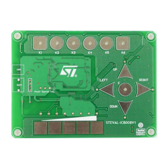
Page 6: Getting Started With Stm8S207S8 Rc Touch Solution
Figure 3 shows the top view of the demonstration board and Figure 4 shows the bottom view. Figure 3. STM8S207S8 RC touch board top view Figure 4. STM8S207S8 RC touch board bottom view 6/31 Doc ID 17987 Rev 2 www.BDTIC.com/ST... - Page 7 PC GUI program. Please refer to the AN2869 application note. STM8S207S8, STMicroelectronics' standard 8-bit microprocessor. SWIM port The SWIM port is reserved for debug use. Please refer to Figure 5 for the pin assignment. Doc ID 17987 Rev 2 7/31 www.BDTIC.com/ST...
-
Page 8: Figure 5. Swim Port Pin Bottom View
Getting started with STM8S207S8 RC touch solution UM1002 Figure 5. SWIM port pin bottom view USB connector The USB connector is a mini-B receptacle for USB standard-A to mini-B cable. 8/31 Doc ID 17987 Rev 2 www.BDTIC.com/ST... -
Page 9: Pc Gui Program
CP2102 manufactured by Silicon Laboratories Inc. Before starting communication, a driver ® needs to be installed on Windows . Please follow the procedures below: ● Step 1: run “CP210x_VCP_Win98SE.exe” in the disc, and click “Next” to proceed. Figure 6. Driver installation step 1 Doc ID 17987 Rev 2 9/31 www.BDTIC.com/ST... -
Page 10: Figure 7. Driver Installation Step 2
Step 2: accept the license agreement and click “Next” to proceed. Figure 7. Driver installation step 2 ● Step 3: choose the installation directory and click “Next” to proceed. The default directory is “c:\SiLabs\MCU\CP210x”. Figure 8. Driver installation step 3 10/31 Doc ID 17987 Rev 2 www.BDTIC.com/ST... -
Page 11: Figure 9. Driver Installation Step 4
UM1002 PC GUI program ● Step 4: click “Install” to proceed. Figure 9. Driver installation step 4 ● Step 5: click “Finish” to exit installation program. Figure 10. Driver installation step 5 Doc ID 17987 Rev 2 11/31 www.BDTIC.com/ST... -
Page 12: Figure 11. Driver Installation Step 6
Step 6: connect the demonstration board to the PC with the USB cable. New hardware is detected. Figure 11. Driver installation step 6 ● Step 7: choose “No, not this time” in “Found New Hardware Wizard”, and click “Next” to proceed. Figure 12. Driver installation step 7 12/31 Doc ID 17987 Rev 2 www.BDTIC.com/ST... -
Page 13: Figure 13. Driver Installation Step 8
Step 8: choose “Install from a list or specific location (Advanced)”, and click “Next” to proceed. Figure 13. Driver installation step 8 ● Step 9: browse the directory where the driver is installed, and click “Next” to proceed. Figure 14. Driver installation step 9 Doc ID 17987 Rev 2 13/31 www.BDTIC.com/ST... -
Page 14: Figure 15. Driver Installation Step 10
Step 10: install “CP210x USB Composite Device” by clicking “Continue Anyway”. Figure 15. Driver installation step 10 ● Step 11: click “Finish” to complete driver installation for “CP210x USB Composite Device”. Figure 16. Driver installation step 11 14/31 Doc ID 17987 Rev 2 www.BDTIC.com/ST... -
Page 15: Figure 17. Driver Installation Step 12
Step 12: another new hardware is detected. Figure 17. Driver installation step 12 ● Step 13: choose “No, not this time” in “Found New Hardware Wizard”, and click “Next” to proceed. Figure 18. Driver installation step 13 Doc ID 17987 Rev 2 15/31 www.BDTIC.com/ST... -
Page 16: Figure 19. Driver Installation Step 14
Step 14: choose “Install from a list or specific location (advanced)”, and click “Next” to proceed. Figure 19. Driver installation step 14 ● Step 15: browse the directory where the driver is installed, and click “Next” to proceed. Figure 20. Driver installation step 15 16/31 Doc ID 17987 Rev 2 www.BDTIC.com/ST... -
Page 17: Figure 21. Driver Installation Step 16
Step 16: install “CP210x USB to UART Bridge Controller” by clicking “Continue Anyway”. Figure 21. Driver installation step 16 ● Step 17: click “Finish” to complete driver installation for “CP210x USB to UART Bridge Controller”. Figure 22. Driver installation step 17 Doc ID 17987 Rev 2 17/31 www.BDTIC.com/ST... -
Page 18: Figure 23. Driver Installation Step 18
The port number is assigned by Windows automatically (or reassigned manually). Note: Never assign a number exceeding 8, otherwise the PC GUI program is not able to recognize the COM port correctly. Figure 23. Driver installation step 18 18/31 Doc ID 17987 Rev 2 www.BDTIC.com/ST... -
Page 19: Pc Gui Program
However, full mode records all touch-sensing information received from the demonstration board. Data is saved in “STM8S RC Touch Demo_Simple.log” and “STM8S RC Touch Demo_Full.log” respectively, which are located in the same directory as the PC GUI Doc ID 17987 Rev 2 19/31 www.BDTIC.com/ST... - Page 20 Key6. The meaning of the table content is the same as slider touch-sensing information. 10. Key illustration Once a touch of the Key electrode is detected, the corresponding icon turns to red. If no touch of the key is detected, the icon remains gray. 20/31 Doc ID 17987 Rev 2 www.BDTIC.com/ST...
-
Page 21: Configuration Dialog
If no other touch is detected, STM8S207S8 once more returns to low power mode. When entering into low power mode, the indication LED “System”, on the demonstration board, slows down its blinking frequency, and the refreshing rate of the PC GUI program also decreases. Doc ID 17987 Rev 2 21/31 www.BDTIC.com/ST... - Page 22 This parameter can take a value varying from -1 to -128. A low absolute value results in high sensitivity for the recalibration. A high absolute value results in low sensitivity for the recalibration. 22/31 Doc ID 17987 Rev 2 www.BDTIC.com/ST...
-
Page 23: Figure 26. Pop-Up Box For Successful Reading Operation From Demonstration Board
After pressing this button, all the 12 configuration parameters described in Configuration Parameters are loaded to the demonstration board from the current dialog. A pop-up box (in Figure 27) shows the operation is successful. Doc ID 17987 Rev 2 23/31 www.BDTIC.com/ST... -
Page 24: Figure 27. Pop-Up Box For Successful Writing Operation To Demonstration Board
Configuration Parameters are saved in the file “STM8S RC Touch Demo.ini” from the demonstration board. The saved file “STM8S RC Touch Demo.ini” is located in the same directory as the PC GUI program. 24/31 Doc ID 17987 Rev 2 www.BDTIC.com/ST... -
Page 25: Appendix A Data Format Of Log Files
In full logging mode, each record value is saved in Key1 → Key2 → Key3 → Key4 → Key5 → Key6 → Up → Left → Down → Right → Center → Slider. Doc ID 17987 Rev 2 25/31 www.BDTIC.com/ST... -
Page 26: Appendix B Schematics
Schematics UM1002 Appendix B Schematics Figure 28. LED indication circuit 26/31 Doc ID 17987 Rev 2 www.BDTIC.com/ST... -
Page 27: Figure 29. Touch Key And Driven Shield
SL IDER3 SL DR3 3.3M SL IDER4 SL DR4 3.3M SL IDER5 SL DR5 L OAD Copper SHI E L D on board SH_DRV SHI EL D PA_DRVSHD 1nF/16V PB_DRVSHD PC_DRVSHD PE_DRVSHD AM06713v1 Doc ID 17987 Rev 2 27/31 www.BDTIC.com/ST... -
Page 28: Figure 30. Mcu And Usb To Uart
PD0 (HS)/TI M3_CH2 [TI M1_BK IN] [ CLK _CCO] CROSS_CENTER PE_DRVSHD [TI M1_CH2N] AI N1/PB1 PE0 (HS)/CL K _CCO PB_DRVSHD CL K [TI M1_CH1N] AI N0/PB0 PE1 (T)/I 2C_SCL SWI M CROSS_L EF T AI N9/PE6 PE2 (T)/I 2C_SDA NRST VDD_MCU SWI M VDD_MCU 0.1uF/16V AM06714v1 www.BDTIC.com/ST... -
Page 29: Figure 31. Power Supply +5 V And +3.3 V
UM1002 Schematics Figure 31. Power supply +5 V and +3.3 V VDD_MCU 22uF/16V 22uF/16V 0.1uF/16V 0.1uF/16V L D1117S33CTR AM06717v1 Figure 32. LED indicator AM06715v1 Doc ID 17987 Rev 2 29/31 www.BDTIC.com/ST... -
Page 30: Revision History
Revision history UM1002 Revision history Table 4. Document revision history Date Revision Changes 16-Nov-2010 Initial release. 14-Dec-2010 Added: Appendix B: Schematics 30/31 Doc ID 17987 Rev 2 www.BDTIC.com/ST... - Page 31 No license, express or implied, by estoppel or otherwise, to any intellectual property rights is granted under this document. If any part of this document refers to any third party products or services it shall not be deemed a license grant by ST for the use of such third party products or services, or any intellectual property contained therein or considered as a warranty covering the use in any manner whatsoever of such third party products or services or any intellectual property contained therein.
Need help?
Do you have a question about the STEVAL-ICB008V1 and is the answer not in the manual?
Questions and answers