
Related Manuals for Perlesmith PSMFK1


Summary of Contents for Perlesmith PSMFK1
- Page 1 Full Motion TV Mount Instruction Manual Model: PSMFK1 For any parts enquiries, please contact AV Supply Group as below: New Zealand: P: 64 9 274 9172 E: info@avsupply.co.nz Australia: P: 61 3 9071 4585 E: info@avsupplygroup.com.au...
- Page 2 Please carefully read all instructions before attempting installation. If you do not understand the instructions or have any concerns or questions, please contact customer service at supportus@perlesmith.com. CAUTION: Avoid potential personal injuries and property damage! • Do not use this product for any purpose that is not explicitly specified in this manual.
-
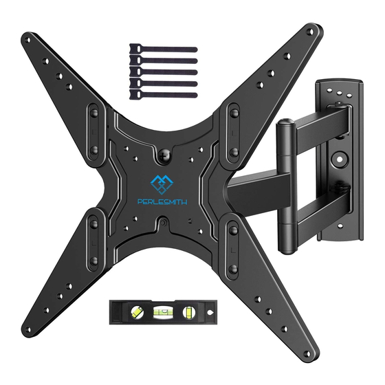
Page 3: Supplied Parts And Hardware
Before starting assembly, verify all parts are included and undamaged. Do not use damaged or defective parts. lf you require replacement parts, please contact customer service at supportus@perlesmith.com. • PLEASE NOTE: Not all hardware included in this package will be used. - Page 4 TV Bolts (Only one bolt size fits your TV) NOTE: The bolts are shown in actual size. [D1] x4 [E1] x4 [E2] x4 M4 X 30mm M6x15mm M6x35mm [F3] x4 [F1] x4 [F2] x4 M8x20mm M8x35mm M8x50mm Supplied Parts and Hardware for Step 3 NOTE: The lag screw is shown in actual size.
- Page 5 Option A: No Need to Attach Extender Brackets to Faceplate 200mm 100mm For VESA hole pattern: 75mm 3x3 in (75x75 mm) 4x4 in (100x100 mm) 4x5.9 in (100x150 mm) 4x7.9 in (100x200 mm) 7.9x4 in (200x100 mm) 7.9x5.9 in (200x150 mm) 7.9x7.9 in (200x200 mm) Option B: Need to Attach Extender Brackets to Faceplate 400mm...
- Page 6 Please Note: When using the spacers it is important to note that they can be used in multi-layers (meaning stacked). If you have any difficulty undestanding how to install the TV bolts or spacers, please contact customer service at supportus@perlesmith.com.
- Page 7 CAUTION: Ensure the faceplate [01A] or faceplate [01A] with extender brackets [02] and [03] is EQUALLY CENTERED on your TV and securely fastened in place. PLEASE NOTE: The bolt hole locations on your TV may vary in accordance of the manufacturers design of the TV.
- Page 8 Option D For cable interference or inset holes, use spacers [05] to create extra space between the TV and the faceplate. C1/C2/C3 D1/E2/F2/F3 (If needed) Alternate Spacer Setups When you finish securing the 7/16 in (11mm) TV bolts into the TV, please Socket Wrench remember to tighten the nuts [H] using a socket wrench.
- Page 9 3A-1 Use a stud finder (not included) to locate wood studs or use an awl (not included) to verify the edges. Mark the edge and center locations. (Not included) 3A-2 Position the Wall Plate Template [07] at your desired height and line up the holes with your stud center line.
- Page 10 Step 3B Solid Concrete or Concrete Block Option WARNING: Avoid potential personal injury or property damage! DO NOT over-tighten the lag screws [A1]. Tighten the lag screws [A1] only until they are pulled firmly against the arm assembly/wall plate [01B]. Wall Ensure the arm assembly/wall plate [01B] is securely Anchor...
- Page 11 3/8 in (10mm) 3B-4 HEAVY! You may need Socket Wrench assistance with this step. (Not lncluded) Install wall plate using lag screws [A1]. Tighten the lag screws [A1] only until they are pulled firmly against the arm assembly/ wall plate [01B]. DO NOT over-tighten the lag screws [A1].
-
Page 12: Tilt Adjustment
Step 5 Adjustments 5-1 Level Adjustment If needed, the TV can be levelled. CAUTION! Phillips Please do not over-tighten Screwdriver or over-loosen the bolts. (Not lncluded) Tighten the bolt [S1] Slightly loosen Level your TV to secure TV in place the bolt [S1] 5-2 Tilt Adjustment 1.
Need help?
Do you have a question about the PSMFK1 and is the answer not in the manual?
Questions and answers