Advertisement
Quick Links
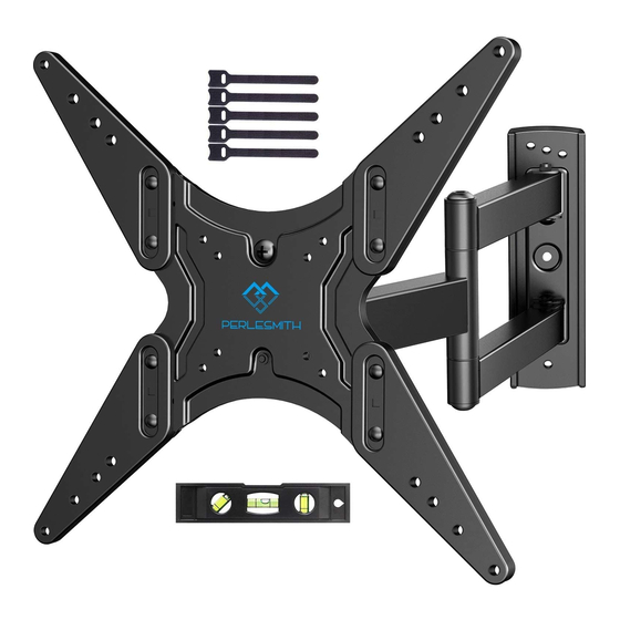
Medium Full Motion TV Mount
Website:
www.perlesmith.com
Instruction Manual
Model: PSMFK1
Thank you for choosing this Perlesmith product! At Perlesmith we strive to
provide you with the best quality products and services in the industry.
Please share your experience of our product with others at
www.perlesmith.com/pages/reviews if you are satisfied. Should you have
any issues, please don't hesitate to contact us.
Technical Support:
1-800-556-6806 Mon-Fri 10am - 5pm (PST) (USA) (CAN)
Other Info:
supportus@perlesmith.com (US)
supportca@perlesmith.com (CA)
V4.0
Advertisement

Subscribe to Our Youtube Channel
Related Manuals for Perlesmith PSMFK1


Summary of Contents for Perlesmith PSMFK1
- Page 1 Instruction Manual V4.0 Model: PSMFK1 Thank you for choosing this Perlesmith product! At Perlesmith we strive to provide you with the best quality products and services in the industry. Please share your experience of our product with others at www.perlesmith.com/pages/reviews if you are satisfied. Should you have any issues, please don't hesitate to contact us.
-
Page 2: Important Safety Information
If your TV VESA is greater than 400x400 mm/16x16in. or less than VESA 100x100mm/4x4 in., this mount is NOT compatible. If this mount is NOT compatible, please contact customer service at supportus@perlesmith.com (US)/ supportca@perlesmith.com (CA) to find a compatible mount. Verify Your Wall Construction... -
Page 3: Supplied Parts And Hardware
Technical Support line at 1-800-556-6806 or customer service at supportus@perlesmith.com (US)/ supportca@perlesmith.com (CA). • Please note: Not all hardware included in this package will be used. Supplied Parts and Hardware for Step 1... - Page 4 Supplied Parts and Hardware for Step 2 Spacers (if needed) Note: The spacers are shown in accordance Washer (if needed) with the actual size [B] x4 M4/M6 [C1] x8 [C2] x4 [C3] x4 φ8.5x18x2.5mm φ8.5x18x10mm φ8.5x18x22mm TV Bolts (Only one bolt size fits your TV) Note: The bolts are shown in accordance with the actual size [D1] x4 [E1] x4...
- Page 5 Note: The lag screws are shown in accordance with the actual size Lag Screw ST6.3x60 mm CAUTION! Wall These anchors are for Anchor concrete or brick walls ONLY. DO NOT use them in drywall or wood studs. Step 1 Secure the Extender Brackets to Faceplate (Optional) Use the phillips screwdriver to remove the bolt [S1] from the faceplate [01A] and keep the bolt [S1] for use in Step 4.
- Page 6 Option B Need to Attach Extender Brackets [02] and [03] to Faceplate [01A]. 3/8in.(10mm) Socket Wrench (Not lncluded) 400mm 300mm 400mm For VESA hole pattern: For VESA hole pattern: 15.7x11.8 in. (400x300 mm) 11.8x11.8 in. (300x300 mm) 15.7x15.7 in. (400x400 mm) 400mm 300mm For VESA hole pattern:...
- Page 7 Correct Note: If necessary, the spacers can be used in multi-layer. If the installation fails after trying various methods, please contact customer service at supportus@perlesmith.com (US)/ supportca@perlesmith.com (CA). CAUTION: Ensure the faceplate [01A] or faceplate [01A] with extender brackets [02] and [03] is EQUALLY CENTERED on your TV AND securely fastened in place.
- Page 8 Option C (For TV with A “Bump”) Spacers may be necessary for 2 holes ONLY. D1/E1/F1 D1/E2/F2/F3 (If needed) (If needed) C1/C2 C1/C2/C3 Alternate Alternate Spacer Spacer Setups Setups Option D For cable interference or inset holes, use spacers [05] to create extra space between the TV and the faceplate.
- Page 9 3A-1 Use a stud finder(not included) to locate wood studs or use an awl (not included) to verify the edges. Mark the edge and center locations. (not included) 3A-2 Position the arm assembly/ wall plate [01B] at your desired height and line up the holes with your stud center line.
- Page 10 Step 3B Solid Concrete or Concrete Block Option WARNING: Avoid potential personal injury or property damage! DO NOT over-tighten the lag screws [A1]. Tighten the lag screws [A1] only until they are pulled firmly against the arm assembly/wall plate [01B]. Wall Anchor Ensure the arm assembly/wall plate [01B] is securely...
- Page 11 3B-3 Use the hammer to knock Install wall plate using lag screws [A1]. anchors [A2] into the wall. Tighten the lag screws [A1] only until they Be sure the anchors [A2] are pulled firmly against the arm assembly/ are seated flush with the wall plate [01B].
-
Page 12: Tilt Adjustment
Step 5 Adjustments 5-1 Level Adjustment If needed, the TV can be levelled. Loosen the bolt [S1] Level your TV Tighten the bolt [S1] to secure TV in place 5-2 Tilt Adjustment 1. Loosen four preassembled nuts. 2. Adjust the TV to the desired tilting angle. 3.
Need help?
Do you have a question about the PSMFK1 and is the answer not in the manual?
Questions and answers