Table of Contents
Advertisement
Quick Links
Model 1130-019 ..................................................... Tiger HP
Model 1130-025 ............................ Tiger HP
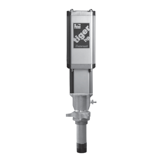
Model 1130-026* .................. Tiger HP
Model 1160-007 ................................. Tiger HP
Operation, Installation, Maintenance and Repair Guide
Tiger HP
®
Bare Oil Pump, 6:1, Flange Mount
®
Bare Oil Pump, 6:1, with Bung Adapter
Bare Stainless Steel Pump, 6:1
®
*Model 1130-026 shown
Thoroughly read and understand this manual before install-
ing, operating or servicing described equipment.
Service Bulletin SB 1065
Rev Q 12/15
®
Oil Pump Series
®
Bare Oil Pump, 6:1
®
Advertisement
Table of Contents

Subscribe to Our Youtube Channel
Related Manuals for Balcrank Tiger HP 1130-019


Summary of Contents for Balcrank Tiger HP 1130-019
-
Page 1: Cover
Service Bulletin SB 1065 Rev Q 12/15 ® Tiger HP ® Oil Pump Series ® Model 1130-019 ............. Tiger HP Bare Oil Pump, 6:1 ® Model 1130-025 ......Tiger HP Bare Oil Pump, 6:1, Flange Mount ® Model 1130-026* ....Tiger HP Bare Oil Pump, 6:1, with Bung Adapter Model 1160-007 ......... -
Page 2: General Safety Information
General Safety Thoroughly read and understand this manual before WARNING installing, operating or servicing the described prod- ucts. WARNING: The Tiger HP 6:1 pump (1130- ® IMPORTANT 019, 1130-025, & 1160-007) develops 790 psi (51.7 Bar) maximum working pressure at 150 psi (10.3 Bar) maximum inlet air pressure and Because this pump can be incorporated stall conditions. -
Page 3: Table Of Contents
Table of Contents Cover ..............1 Pump Repair/Servicing ........5-8 General Safety Information........2 Troubleshooting Guide .......... 9 Product Description ..........3 Parts List.............. 10 Technical Data ............3 Parts Diagrams ..........11-16 Pump Installation ........... 4 Pump Dimensions ..........17 Operation ............... -
Page 4: Pump Installation
® pipe bushing or adapter (to bring the line drop using a reservoir bung fi tting and Balcrank Universal size to 3/4" male) Bung Adapter, model 4411-009N. 2); foot mount to a 1/2" pipe drop to pump level reservoir bung fi... -
Page 5: Preventive Maintenance
Contact your local Balcrank distributor, using the above Slowly adjust the air regulator until the pump is part number, for replacement grease. primed and running smoothly. Be sure all air has been purged from the system. - Page 6 along with the four 5/16" Hex Bolts [31] and Lockwash- the Air Piston plus Rod Coupler, items [17] and [29], ers [4] which secure them. from the vise and set aside. Note! It is not necessary to separate the joint of the Air Piston and Coupler. Mount the Air Motor horizontally in a bench vise.
- Page 7 For the 1160-007, remove screws [55] and lock- Set this subassembly aside. washers [54] with a 7/16" wrench. For all models, Figure 8 using snap ring pliers, remove the Retaining Ring [40] from the Fluid Adapter [33]. Then remove the Cup Seal Collect the parts group shown in fi...
- Page 8 to 40 in-lb torque. Use vise grips, applied near the Rod Install the O-ring Seal [2] into the gland in the Cap [9]. Install the Cap [9] on the top of the Air Head, to turn the Trip Rod. Motor. When the Cap [9] is installed, it must be shifted Install the following items onto the Trip Rod [16] sideways approximately 1 inch to allow attachment of in the sequence and orientation shown in fi...
-
Page 9: Troubleshooting Guide
Troubleshooting Guide WARNING: Before beginning pump repair, NOTE: Check all other possible causes of all internal pressure must be relieved. To reduce operating problems, and apply remedial action, risk of personal injury, follow the Pressure Relief before disassembling pump. Procedure shown on pages 2 and 5. Trouble Probable Cause Corrective Action... -
Page 10: Parts List
Service Kits 900020 Pump Lower Rebuild Kit Parts List 900027 Air Motor Rebuild Kit (*see note) 900028 Air Motor Soft Parts Kit (*see note) Tiger HP 6:1 Ratio Pump ® 828070 SS Pump Lower Rebuild Kit Part Pump Service Part Pack Item Number Description... -
Page 11: Parts Diagrams
Part Pump Item Description Service Kit Qty Part Pack Kits Number 829002 Lock Washer 829001 Screw Hex Hd, 1/4-20 x 0.75 Long 833052 Valve, Pressure Relief, 850 psi 833189 Kit, Pressure Relief Hose Green 638 Red 263 Green 638 Figure 2 Head Assembly Assembly Stage 1 Red 263... - Page 12 Green 638 White 567 1 drop only Green 638 Figure 4 Exploded Views Head Assembly Tiger HP 6:1 Ratio Pump Assembly Stage 3 ® Air Motor - Item number, see page 10 - Grease application point, see detail in written procedure - Loctite application point, see detail in written procedure...
- Page 13 Green 638 Exploded Views Tiger HP 6:1 Ratio Pump ® Air Motor Figure 5 Head Assembly - Item number, see page 10 Assembly Stage 4 - Grease application point, see detail in written procedure - Loctite application point, see detail in written procedure...
- Page 14 Red 263 1160-007 1130-019 Red 263 Red 263 Figure 7 Bare Pump Assembly Assembly Stage 6 Figure 6 Bare Pump Assembly Assembly Stage 5 1130-019 1160-007 Exploded Views Tiger HP ® 6:1 Ratio Pump Lower Assembly - Item number, see page 10 - Grease application point, see Figure 8 detail in written procedure...
- Page 15 Red 263 1 drop only Figure 9 Bare Pump Assembly Assembly Stage 8 Figure 10 Bare Pump Assembly Assembly Stage 9 Exploded Views Tiger HP 6:1 Ratio Pump ® Lower Assembly - Item number, see page 10 - Grease application point, see detail in written procedure - Loctite application point, see detail in written procedure...
- Page 16 48 50 Complete Air Motor Figure 12 Subassembly Flange Mount Parts Detail for Model 1130-025 Only Complete Lower Pump Subassembly Flange Mount Bolt Pattern Figure 11 for Model 1130-025 Only Final Pump Assembly Assembly Stage 10 Exploded Views - Item number, see page 10 Tiger HP 6:1 Ratio Pump ®...
-
Page 17: Pump Dimensions
5.82 0.625 10.46 3/8" NPT(F) Air Inlet Port 3/4" NPT(F) 4.81 Fluid Outlet Port 25.72 1.58 16.88 5.25 Dia Hole Circle 9.11 4.12 1.55 1"" NPT(F) and 1-1/2" NPT(M) Fluid Inlet Port Mounting Flange. Use with four 5/16" Bolts 2.13 Model 1130-025 Flange Mount Version Figure 13... - Page 18 Accessories 4411-024N 4411-009N 4411-018N Universal Bung Adapter Double Tapped Bushing 2" PVC collar for fi ll port 4411-017 Nickel Plated Bung Adapter (1) Nickel plated bung adapter (for use with model 1160-007 Tiger HP Stainless Steel Pump)
-
Page 19: Warranty Statement
NOTES: Revision Log: Rev. A - 5/05 - New Release Rev. B - 5/06 - Added 1160-007 Rev C - 4/07 - Changed Part #'s page 10 (Item 1,5) Rev D - 6/07 - Added Loctite "638" Identifi er to pg 7. Rev E - 12/08 - Removed part 828817 and changed part numbers for items 54 &... - Page 20 For Warranty Information Visit: www.balcrank.com Balcrank Corporation ® Weaverville, NC 28787 800-747-5300 800-763-0840 Fax www.balcrank.com Service Bulletin SB 1065 Rev. Q 12/15...
Need help?
Do you have a question about the Tiger HP 1130-019 and is the answer not in the manual?
Questions and answers