Table of Contents
Advertisement
Quick Links
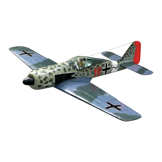
W.W2 GERMAN FIGHTER
Instruction manual / Montageanleitung
SPECIFICATIONS
Wingspan:............................1500mm (59in)
Length:..............................1130mm (44.5 in)
Electric Motor:.....................See next pager
Glow Engine:.................... .46 2-T / .70 4-T
RTF Weight: 3.2Kg / 7.05lbs (Will vary with
Equipment Used).
Radio:.................6-8 Channels / 6-7 Servos
Function: Ailerons-Flaps-Elevator-Rudder-Throttle
Optional Retractable Landing Gear.
WARNING! This radio controlled model is NOT a toy. If modified or flown carelessly it could go out of controll and
cause serious human injury or property damage. Before flying your airplane, ensure the air field is spacious enough.
Always fly it outdoors in safe areas and seek professional advice if you are unexperienced.
ACHTUNG! Dieses ferngesteuerte Modell ist KEIN Spielzeug! Es ist für fortgeschrittene Modellflugpiloten bestimmt,
die ausreichende Erfahrung im Umgang mit derartigen Modellen besitzen. Bei unsachgemässer Verwendung kann
hoher Personen- und/oder Sachschaden entstehen. Fragen Sie in einem Modellbauverein in Ihrer Nähe um
professionelle Unterstätzung, wenn Sie Hilfe im Bau und Betrieb benötigen. Der Zusammenbau dieses Modells ist
durch die vielen Abbildungen selbsterklärend und ist für fortgeschrittene, erfahrene Modellbauer bestimmt.
Radio control model / Flugmodel
ALL BALSA, PLYWOOD CONSTRUCTION AND ALMOST READY TO FLY
Advertisement
Table of Contents

Subscribe to Our Youtube Channel
Related Manuals for Nexa Focke Wulf FW-190A


Summary of Contents for Nexa Focke Wulf FW-190A
- Page 1 Radio control model / Flugmodel W.W2 GERMAN FIGHTER ALL BALSA, PLYWOOD CONSTRUCTION AND ALMOST READY TO FLY Instruction manual / Montageanleitung SPECIFICATIONS Wingspan:......1500mm (59in) Length:......1130mm (44.5 in) Electric Motor:.....See next pager Glow Engine:.....46 2-T / .70 4-T RTF Weight: 3.2Kg / 7.05lbs (Will vary with Equipment Used).
- Page 2 Read through the manual before you begin, so you will have an overall idea of what to do. OPTIONAL ACCESSORIES / BENOTIGTES ZUBEHOR 10.5x6 for .40 - 2 cycle engine Extension for aileron 11x6 for .46 - 2 cycle engine flap and retract servo.
-
Page 3: Aileron And Flap Servo Installation
1-Aileron extension cord installation SAFETY NOTES BEFORE ASSEMBLING WING BOTTOM-VIEW This model is highly pre-fabricated and can be built in a very short time. However, the work which you have to carry out is important and must be done carefully. Extension cord The model will only be strong and fly well if you complete your tasks competently - so please work... - Page 4 3- Control horn & linkages Plastic control horn ....2 set Plastic control horn ....2 set 2x20mm screw ..4 2mm connector ....4 2x175mm push rod ....4...
-
Page 5: Joining The Wing
4- Joining the wing Draw the center line on the wing joiner Before gluing: - Draw the center line on the wing joiner. - Trial fit each part before gluing . Be certain that there are no gaps. If the parts will join, but with a gaps, sand or trim the parts a little at a time until the parts meet exactly with no gaps. - Page 6 5- Fixed gear assembly Insert the main landing gear into the slot on the gear mount, if necessary, use sander to widen the slot to Remove the nylon gear Reposition the nylon gear Using the nylon gear strap make this easier. strap and drill a 2mm hole strap and secure them in as a template, mark the...
-
Page 7: Fixed Gear Installation
6- Fixed gear installation 3x12mm screw 3x12mm screw 3x12mm screw ..8 Attach the plastic wheel well cover in place and secure it with litter CA glue or 2x8mm screws. - Page 8 7- Fixed gear installation continued ...2 Hex wrench 4mm collar ..2...
- Page 9 8- Fixed gear installation continued 1.5mm Plastic track 2x6mm screw ..4 9- Attach the wing to the fuselage 6x40mm nylon bolt ..2...
-
Page 10: Horizontal Stabilizer
10- Horizontal stabilizer Full the elevator out of the horizontal stabilizer. Cut away only the covering. Cut away only the covering both sides. Insert the horizontal stabilizer into the slot on the fuselage, if necessary, use sander to widen the slot to make this easier. A’... -
Page 11: Vertical Stabilizer
11- Horizontal stabilizer continued Remove the horizontal stabilizer from the fuselage. Using the sharp hobby knife, carefully cut away the Cut away only the covering inside the lines which were marked above. covering inside the line. Be cautious not to cut into the wood, this will weaken the structure. - Page 12 13- Vertical stabilizer continued When you are satisfied with the alignment, use a pencil to trace around the right and left of the stabilizer where the vertical stabilizer meet the fuselage. Remove the vertical stabilizer from the fuselage. Using the sharp hobby knife, carefully cut away the covering inside the lines which were marked above.
- Page 13 14- Elevator and Rudder control horn Plastic control horn ....3 2x12mm screw ....6 Thin CA ! Securely glue together. If coming off during fly, you lose control of your air plane. Note: make sure the rudder move freely without binding.
-
Page 14: Tail Wheel
15- Tail wheel 3x12mm screw 1.5mm 2x15mm screw 16- Glow engine ! Align the mark on both engine mount beams with the mark on the firewall. ! Engine thrust on balk head is already adjust at factory FRONT-VIEW B=B’ Mark on the firewall B’... - Page 15 17- Glow engine continued 4x25mm hex bolt ..4 Blind-nut ....4 Insert the blind-nut onto each of the four holes make 4mm washer above.....4 Reposition the engine mount beams on to the fire-wall and secure them with four 4x25mm hex bolt. 3x20mm screw ...4 .....4...
-
Page 16: Electric Motor
19- Electric motor Using a aluminum motor mounting plate Remove the aluminum motor mounting as a template, mark the plywood motor plate and drill a 3mm hole through mounting plate where the four holes are the plywood at each of the four marks to be drilled. - Page 17 20- Cowling Attach the board or transparent plastic on the side of Adhesive the fuselage with the adhesive tape as show. tape Using a pencil or felt tipped pen trace around the engine head where it meets the cowl. Cut the opening the board or transparent plastic for the engine head as marked above.
- Page 18 22- Decor 30mm Magnetic fuel tank hatch Drill the 4mm hole and 3mm deep before attaching the plastic gun barrel. 45mm x4pcs...
-
Page 19: Control Surface
23- Balance and control surface THE CENTER OF GRAVITY IS LOCATED 107mm BACK FROM THE LEADING EDGE OF THE WING, AT THE FUSELAGE. BALANCE A PLANE UPSIDE DOWN WITH THE FUEL TANK EMPTY. 107mm 1- Mount the wing to the fuselage. Using a couple of pieces of masking tape, place them on the top side of the wing (107mm) back from the leading edge, at the fuselage sides.
Need help?
Do you have a question about the Focke Wulf FW-190A and is the answer not in the manual?
Questions and answers