Table of Contents
Advertisement
Quick Links
User's Guide
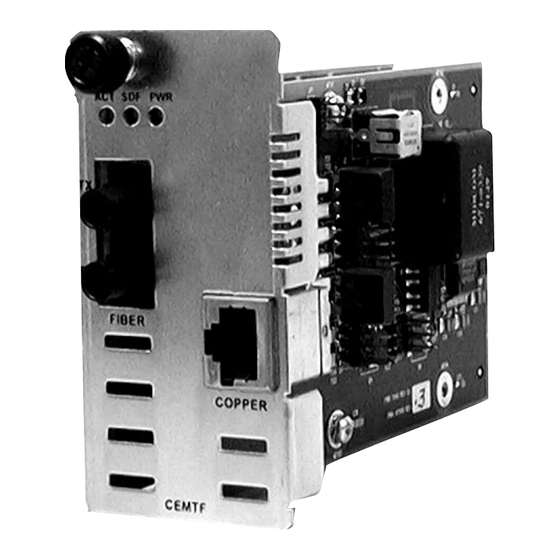
CEMTF10xx-10x
Slide-in-Module Device
E&M 2/4 Wire to Fiber
Transition Networks CEMTF10xx-10x series E&M 2/4
Wire-to-Fiber Device connects central-office voice
grade signals to distant PBX (Private Branch eXchange)
equipment utilizing E&M signaling. The Device provides
complete electrical isolation for 2- or 4-wire voice path
cable in areas of high electrical noise or where high
security is required.
Product Number
Port One - Copper
CEMTF1011-100
RJ-45
5 km (3.1 miles)*
CEMTF1013-100
RJ-45
5 km (3.1 miles)*
CEMTF1014-100
RJ-45
5 km (3.1 miles)*
CEMTF1015-100
RJ-45
5 km (3.1 miles)*
Part Number
Port One - Copper
CEMTF1029-100
RJ-45
5 km (3.1 miles)*
CEMTF1029-101
RJ-45
5 km (3.1 miles)*
CEMTF1029-102 and -103 are intended to be installed in the same network.
CEMTF1029-102
RJ-45
5 km (3.1 miles)*
CEMTF1029-103
RJ-45
5 km (3.1 miles)*
CEMTF1029-100 and -101 are intended to be installed in the same network.
* Typical maximum cable distance. Actual
distance is dependent upon the physical
characteristics of the network
installation.
Port Two - Fiber-Optic
ST, 1300 nm multimode
2 km (1.24 miles)*
SC, 1300 nm multimode
2 km (1.24 miles)*
SC, 1310 nm single mode
20 km (12.4 miles)*
SC, 1310 nm single mode
40 km (24.9 miles)*
Port Two - Fiber-Optic
single-fiber single mode
SC, 1310 (TX) / 1550 (RX) nm
20 km (12.4 miles)*
SC, 1550 (TX) / 1310 (RX) nm
20 km (12.4 miles)*
SC, 1310 (TX) / 1550 (RX) nm
40 km (24.8 miles)*
SC, 1550 (TX) / 1310 (RX) nm
40 km (24.8 miles)*
CEMTF10xx-10x in the Network . . .2
Installation . . . . . . . . . . . . . . . . . . . . .3
Operation . . . . . . . . . . . . . . . . . . . .13
Cable Specifications . . . . . . . . . . . . .15
Technical Specifications . . . . . . . . . .16
Troubleshooting . . . . . . . . . . . . . . . .17
Compliance Information . . . . . . . . .18
Advertisement
Table of Contents

Related Manuals for Transition Networks CEMTF1011-100


Summary of Contents for Transition Networks CEMTF1011-100
- Page 1 2- or 4-wire voice path cable in areas of high electrical noise or where high security is required. Product Number Port One - Copper Port Two - Fiber-Optic CEMTF1011-100 RJ-45 ST, 1300 nm multimode 5 km (3.1 miles)* 2 km (1.24 miles)* CEMTF1013-100...
-
Page 2: Installation
CEMTF10xx-10x CEMTF10xx-10x in the Network Install two CEMTF10xx-10x series Devices in series to extend, over fiber, the distance between two voice path communication devices. An E&M signal is used to communicate between a CO (telephone company Central Office) device and a PBX (Private Branch eXchange) device. - Page 3 CEMTF10xx-10x Audio interface (2-wire / 4-wire) There are two types of audio interfaces: 2- wire and 4-wire; which describe the number of wires used to transmit audio signals. The figure to the right illustrates the jumper configurations for the 2-wire and 4-wire implemetations.
- Page 4 CEMTF10xx-10x E&M Signal Type I E&M Signal Type I is the most common interface in North America. Set the jumpers on the “Side A” and “Side B” Devices as follows: * optional Jumper settings for: "Side A" Media "Side B" Media Converter Converter The figure below illustrates the wiring connections for the “Side A”...
- Page 5 CEMTF10xx-10x E&M Signal Type III E&M Signal Type III is not commonly used in modern systems. For this configuration, set the jumpers on the “Side A” Device and the “Side B” Device as follows: Jumper settings for: "Side A" Media "Side B"...
-
Page 6: Install The Slide-In-Module
CEMTF10xx-10x E&M Signal Type V E&M Signal Type V is symmetrical and allows two CO devices (Side B) nodes to be connected back-to-back. This signal type is also the most common interface type used outside North America. For this configuration, set the jumpers on the “Side A”... -
Page 7: Operation
CEMTF10xx-10x Install the Copper Cable Locate or build two custom copper cables with a male, RJ-45 connector at one end and a connector of choice at the other end. Connect the copper cable to the “Side A” Device as described: •... -
Page 8: Cable Specifications
<10-9 Single mode fiber (recommended): 9 µm Multimode fiber (recommended): 62.5/125 µm Multimode fiber (optional): 100/140, 85/140, 50/125 µm CEMTF1011-100 1300 nm multimode Fiber Optic Transmitter Power: min: -19.0 dBm Fiber Optic Receiver Sensitivity: min: -30.0 dBm Link Budget: 11.0 dB... -
Page 9: Technical Specifications
CEMTF10xx-10x Technical Specifications For use with Transition Networks Model CEMTF10xx-10x or equivalent Standards FCC Part 68 Data Rate 25 mhz (over fiber cable) Dimensions 2.9" x 4.8" x 1.4" (74 mm x 122 mm x 36 mm) Weight 8 oz (227 g) approximately Power Consumption 9.0 watts MTBF... -
Page 10: Compliance Information
Transition Networks 10900 Red Circle Drive, MinnetonkaMN 55343 U.S.A. Model: CEMTF10xx-10x Series Devices Part Number(s): CEMTF1011-100, CEMTF1012-100, CEMTF1013-100, CEMTF1014-100, CEMTF1015-100, CEMTF1029-100, CEMTF1029-101, CEMTF1029-102, CEMTF1029-103 Regulation: EMC Directive 89/336/EEC Purpose: To declare that the CEMTF10xx-10x to which this declaration refers is in conformity with the following standards. - Page 11 Trademark Notice All registered trademarks and trademarks are the property of their respective owners. Copyright Restrictions © 2003, 2005 Transition Networks. All rights reserved. No part of this work may be reproduced or used in any form or by any means - graphic, electronic, or mechanical - without written permission from Transition Networks.
Need help?
Do you have a question about the CEMTF1011-100 and is the answer not in the manual?
Questions and answers