Table of Contents
Advertisement
Quick Links
MAINTENANCE
Cat.No.: MAN205-0211-002 Rev: C
Manufactured by:
Tuttnauer Co. Ltd., P.O.Box 35292, Jerusalem, Israel
OPERATION
MANUAL
Prevacuum Steam Heated Autoclave
with Steam to Steam Generator
and Vertical Sliding Door
model 6690 STS-1V
S/N: 2301006, 2301007, 2301011, 2301012, 2301013,
2301014, 2301015, 2301016, 2301017, 2301018
&
Tel: 972 2 6581611,
Fax: 972 2 6520271
Advertisement
Table of Contents
Troubleshooting

Related Manuals for Tuttnauer 6690 STS-1V


Summary of Contents for Tuttnauer 6690 STS-1V
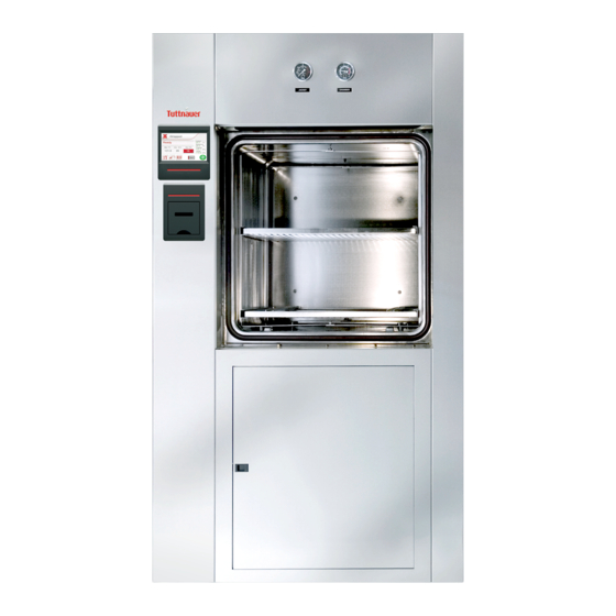
- Page 1 Steam to Steam Generator and Vertical Sliding Door model 6690 STS-1V S/N: 2301006, 2301007, 2301011, 2301012, 2301013, 2301014, 2301015, 2301016, 2301017, 2301018 Cat.No.: MAN205-0211-002 Rev: C Manufactured by: Tuttnauer Co. Ltd., P.O.Box 35292, Jerusalem, Israel Tel: 972 2 6581611, Fax: 972 2 6520271...
-
Page 3: Table Of Contents
Table of Contents Incoming Inspection ---------------------------------------------------------------- 1 1. General Information 1.1 Introduction ---------------------------------------------------------------------- 2-3 1.2 Standards --------------------------------------------------------------------------- 3 1.3 Specifications ----------------------------------------------------------------------- 4 1.4 Steam Data-------------------------------------------------------------------------- 4 2. Functional Description 2.1 The Steam to Steam Generator ----------------------------------------------- 5 2.2 The Water Pump------------------------------------------------------------------- 5 2.3 The Piping System ------------------------------------------------------------- 6-7 2.4 The Pneumatic Control System -------------------------------------------- 8-9 2.5 The Water Quality ---------------------------------------------------------- 10-11... - Page 4 Table of Contents 5.1.1 Temp 1 --------------------------------------------------------------------- 65 5.1.2 Temp 2 --------------------------------------------------------------------- 66 5.1.3 Temp 3 --------------------------------------------------------------------- 66 5.1.4 Temp 4 --------------------------------------------------------------------- 66 5.1.5 Chamber Pres ------------------------------------------------------------ 66 5.1.6 Jacket Pres ---------------------------------------------------------------- 66 5.1.7 Gen Pres ------------------------------------------------------------------- 66 5.1.8 D1 Pres----------------------------------------------------------------- 66-67 6.
- Page 5 Table of Contents 12. Spare Parts ------------------------------------------------------------------ 95-96 13. Valves Numbering -------------------------------------------------------- 97-98 14. Pressure and Temperature Table for Saturated Steam------------ 99 Drawings ♦ The Pneumatic Control System Drawing ------------------------------------- 9 ♦ Vertical Sliding Door------------------------------------------------------------- 100 ♦ Vertical Door- Locking Mechanism ------------------------------------------ 101 ♦...
-
Page 6: Incoming Inspection
For technical information or service please contact our representative at: Tuttnauer USA Co. 25 Power Drive Hauppauge NY, 11788, USA Tel:(800)624 5836, (631)737 4850... -
Page 7: General Information
GENERAL INFORMATION Introduction This autoclave is a pre-vacuum sterilizer designed to cover a large field of applications for hospitals and medical centers as well as pharmaceutical and biotechnological industries. The autoclave operates with saturated steam as the sterilizing agent, and has a temperature of up to 279ºF and pressure up to 40 psi. -
Page 8: Standards
3. Complies with AAMI/ANSE ST8- Hospital Steam Sterilizers. 4. Complies with Underwriters Laboratories (U.L 2601-1) requirements Tuttnauer is approved for ISO 9002 (Quality Systems), EN 46002 (Quality Systems for Medical Devices) and ISO 13488 (Quality systems for Medical devices – Particular requirements for the application of ISO 9002). -
Page 9: Specifications
Specifications Model 6690 – 1V Product data 26’’ (660 mm.) Chamber Dim. 26’’ (660 mm.) 36’’ (1070 mm.) Chamber volume 467 l. 1215 mm. External dim. 1990 mm. 1450 mm. Net Weight 1150 kg (2540 lb) IPX 4 Degree of protection Utilities 1’’, 50-80 PSI, Steam supply... -
Page 10: Functional Description
FUNCTIONAL DESCRIPTION The Steam to Steam Generator The steam for the sterilization process is supplied from the building main steam supply to a built in steam to steam generator, which produces clean steam and is directly connected to the autoclave chamber. Water to the steam generator is supplied by a single-phase pump, from a water reservoir, which is connected to a source of distilled or mineral free water. -
Page 11: The Piping System
The Piping System The piping system of the autoclave consists of air-operated ball valves, which control the water, condensate and steam flow in and out of the chamber, operate the vacuum pump, and the air inlet valve. The air pulses to the pneumatic valves is transmitted through solenoid pilot valves, operated at 24VDC. - Page 12 Vacuum to gasket valve (53); connects the gasket groove to the ejector. While the door is moving during the opening or closing - the valve is open and vacuum is produced to pull the gasket inside the groove, ensuring the smooth sliding of the door.
-
Page 13: The Pneumatic Control System
The Pneumatic Control System The control of the pneumatic valves is done through compressed air, as described below: The pneumatic valves are air-air control type, fitted with two commands, an opening command received through solenoid valve at a pressure of 6 bars - output by the control system and a permanent closing command at a pressure of 3 bars, connected to all valves. -
Page 14: The Pneumatic Control System Drawing
Page 9 of 117 pages... -
Page 15: The Water Quality
Water Quality 2.5.1 Steam to Steam Generator The distilled or mineral – free water supplied to the steam to steam generator should have the physical characteristics and maximum acceptable level of contaminants indicated in the table below: Physical Characteristics and Maximum acceptable contaminants levels in water or steam, for steam generator (In compliance with ISO 11134 and ISO 13683). - Page 16 2.5.3 Reverse Osmosis A Reverse Osmosis (RO) system may be used to improve the quality of the water used to generate steam in the autoclave chamber. In RO, the water is forced through a semi-penetrable membrane, which filters out contaminants to a high degree of efficiency. In deionisation (DI) ions and charged particles are removed either by electric fields or by ion exchange in resin beds.
-
Page 17: The Electric System
The Electric System The electric system of the autoclave comprises of the power circuits, including the commands, switching and protective components, required for the operation of the electric equipment of the machine. The following parts are located in the electric box, mounted on the side of the autoclave. -
Page 18: Control System
Control System The Main Board Contains the electronic microcontroller system, which controls and monitors the physical parameters of the process and performs the operation sequence of the machine according to the selected program. The dimensions of the main board are 30x15x10cm. The main board contains the following elements: ♦... - Page 19 Voltage Inputs for Water Level Electrodes Water level electrodes may be placed at a few points in the autoclave. Due the experience accumulated at “Tuttnauer”, it was determined a maximum of 3 water-level measuring points are required for the sterilization process. The points...
- Page 20 4 Serial Ports The control system contains 4 serial ports according to the following specifications: ♦ Serial Ports for the connection of up to 2 command panels (RS485). ♦ 1 Serial Port connected to an external PC computer (RS232). ♦ 1 Serial Port connected to an internal PC computer that will work as an activating panel (RS232).
-
Page 21: Sterilization Programs
3. STERILIZATION PROGRAMS Following are the names, relevant programs with related temperatures of the 12 sterilization cycles and 2 test programs which are pre-set by the manufacturer. Cycle no. Program Temp. ºF Unwrapped Unwrapped 03 &4 Unwrapped 270/274 Wrapped Wrapped Wrapped Wrapped Liquids... - Page 22 Program: 1- Fast 250 Front door close Msw PT100 Drain Control 5 PT100 Condense 1 PT100 Condense 2 IMT Jacket IMT Chamber Condition to open Open door T<230ºF ; P<115kPa Close door Ejector Buzzer 13 – Cool drain 15 – Water to ejector 43 –...
- Page 23 Program 2 - for Unwrapped goods (Fast 250) This program is intended for unwrapped rigids (like instruments) and other goods, which its manufacturer declares their compliance to be sterilized in the following conditions: ♦ Sterilization temperature 250ºF ♦ Sterilization time: 15 mins. ♦...
- Page 24 Program: 2- Fast 250 Front door close Msw PT100 Drain Control 5 PT100 Condense 1 PT100 Condense 2 IMT Jacket IMT Chamber Condition to open Open door T<230ºF ; P<115kPa Close door Ejector Buzzer 13 – Cool drain 15 – Water to ejector 43 –...
- Page 25 Program 3 & 4 - for Unwrapped goods (Fast 270/274) This program is intended for unwrapped rigids (like instruments) and other goods, which its manufacturer declares their compliance to be sterilized in the following conditions: ♦ Sterilization temperature 270ºF (for program 3) and 274ºF (for program 4) ♦...
- Page 26 Program: 3 & 4 - (Fast 270 / 274) Front door close Msw PT100 Drain Control 5 PT100 Condense 1 PT100 Condense 2 IMT Jacket IMT Chamber Condition to open Open door T<230ºF; P<115kPa Close door Ejector Buzzer 13 – Cool drain 15 –...
- Page 27 Program 5 - for Wrapped goods (with Dry 270) This program is intended for wrapped materials (like instruments), porous load and other goods, which its manufacturer declares their compliance to be sterilized in the following conditions: ♦ Sterilization temperature 270ºF ♦...
- Page 28 Program: 5- for Wrapped goods (with Dry 270) Front door close Msw PT100 Drain Control 5 PT100 Condense 1 PT100 Condense 2 IMT Jacket IMT Chamber Condition to open Open door T<230ºF ; P<115kPa Close door Ejector Buzzer 13 – Cool drain 15 –...
- Page 29 Program 6 - for Wrapped goods (with Dry 270) This program is intended for wrapped materials (like instruments), porous load and other goods, which its manufacturer declares their compliance to be sterilized in the following conditions: ♦ Sterilization temperature 270ºF ♦...
- Page 30 Program: 6- Wrapped goods - with Dry (270) Front door close Msw PT100 Drain Control 5 PT100 Condense 1 PT100 Condense 2 IMT Jacket IMT Chamber Condition to open Open front door T<230ºc ; P<115kPa Close front door Ejector Buzzer 13 –...
- Page 31 Program 7- for Wrapped materials (with Dry 274) This program is intended for wrapped materials (like instruments), porous load and other goods, which its manufacturer declares their compliance to be sterilized in the following conditions: ♦ Sterilization temperature 274ºF ♦ Sterilization time: 7 mins. ♦...
- Page 32 Program: 7- Wrapped goods - with Dry (274) Front door close Msw PT100 Drain Control 5 PT100 Condense 1 PT100 Condense 2 IMT Jacket IMT Chamber Condition to open Open front door T<230ºF ; P<115kPa Close front door Ejector Buzzer 13 –...
- Page 33 Program 8 (with Dry 270) This program is intended for wrapped materials (like instruments), porous load and other goods, which its manufacturer declares their compliance to be sterilized in the following conditions: ♦ Sterilization temperature 270ºF ♦ Sterilization time: 3 mins. ♦...
- Page 34 Program: 8- Wrapped goods - with Dry (270) Front door close Msw PT100 Drain Control 5 PT100 Condense 1 PT100 Condense 2 IMT Jacket IMT Chamber Condition to open Open front door T<230ºF ; P<115kPa Close front door Ejector Buzzer 13 –...
- Page 35 Program 9 - for Liquids (Slow 250) This program is intended for the sterilization of liquids in open or closed containers (but not sealed) and other goods, which its manufacturer declares their compliance to be sterilized in the following conditions: ♦...
- Page 36 Program: 9- Slow 250 Front door close Msw PT100 Drain Control 5 PT100 Condense 1 PT100 Condense 2 IMT Jacket IMT Chamber Condition to open Open front door T<230ºF ; P<115kPa Close front door Ejector Buzzer 13 – Cool drain 15 –...
- Page 37 Program 10 - for Liquids (Slow 250) This program is intended for the sterilization of liquids in open or closed containers (but not sealed) and other goods, which its manufacturer declares their compliance to be sterilized in the following conditions: ♦...
- Page 38 Program: 10- Slow 250 Front door close Msw PT100 Drain Control 5 PT100 Condense 1 PT100 Condense 2 IMT Jacket IMT Chamber Condition to open Open front door T<230ºF ; P<115kPa Close front door Ejector Buzzer 13 – Cool drain 15 –...
- Page 39 Program 11 & 12 - for Liquids (Slow 250) This program is intended for the sterilization of liquids in open or closed containers (but not sealed) and other goods, which its manufacturer declares their compliance to be sterilized in the following conditions: ♦...
- Page 40 Program: 11 & 12 - Slow 250 Front door close Msw PT100 Drain Control 5 PT100 Condense 1 PT100 Condense 2 IMT Jacket IMT Chamber Condition to open Open door T<230ºF ; P<115kPa Close door Ejector Buzzer 13 – Cool drain 15 –...
- Page 41 Program 13 "Bowie & Dick Test” This program is intended to test residual air in the chamber. The parameters are locked in such a way that they can not be changed. These are the parameters: ♦ Sterilization temperature 274ºF ♦ Sterilization time 3.5 mins. ♦...
- Page 42 Program: 13- Bowie & Dick Front door close Msw PT100 Drain Control 5 PT100 Condense 1 PT100 Condense 2 IMT Jacket IMT Chamber Condition to open Open door T<230ºF ; P<115kPa Close door Ejector Buzzer 13 – Cool drain 15 – Water to ejector 43 –...
- Page 43 Program 14 "Air leakage Test” This program is intended to test air leakage to chamber through the door seal or any other seals. This test is performed in vacuum phase. Performance description: Vacuum is built up in the chamber down to 10kPa. At this stage all valves and motors are shut.
- Page 44 Program: 14- Air leakage test Front door close Msw PT100 Drain Control 5 PT100 Condense 1 PT100 Condense 2 IMT Jacket IMT Chamber Condition to open Open door T<230ºF ; P<115kPa Close door Ejector Buzzer 13 – Cool drain 15 – Water to ejector 43 –...
-
Page 45: Control And Monitoring
4. CONTROL AND MONITORING Control Panel ‘CAT 2007’ Page 40 of 117 pages... -
Page 46: Description Of Panel 'Cat 2007
Description of panel 'CAT 2007' The Operation Panel is composed of the following parts: ♦ 4 rows display, 20 characters in each row. ♦ 18 key pads ♦ 2 LED's (Fail, Run) ♦ 1 locking key 4.1.1 Keypad STANDBY The ON/ST.BY key is located on the top right side of the panel. Pressing the keypad lights up the operation panel. - Page 47 Canceling the FAIL message At the end of an aborted process the FAIL light is turned on and an error message is displayed on the screen indicating the cause of the failure. Pressing the STOP key cancels the displayed message and switches off the FAIL light.
-
Page 48: Display
4.1.2 Display The CAT2007 display consists of 4 alphanumeric rows with 20 characters in each row: First Row First 3 characters define the Cycle no. (ranges from 1-14) There are 8 characters to define the Cycle name. The final 5 characters at the right of the row are allocated to displaying the status of the appliance or the stage in which the cycle is found whilst running. - Page 49 Fourth Row: In the bottom row the names of the commanding keypads appear. Under the display there are three keypads without symbols or names These keypads receive their commands by the name that appears above them in the 4th row of the display. During a cycle, the fourth row is used to display the timers, such as STE Time 02:25, or during prevacuum, to display the stage of the pulse, such as puls1 –...
-
Page 50: Description Of Displayed Messages And Safety Measures
Description of Displayed Messages and Safety Measures 03 – Manual Stop Message is displayed and the FAIL indicator lights after the STOP key is pressed for more than 1 second during the cycle (excluding the drying stage). 100 – Man.Stop This message is displayed and the FAIL indicator lights after the STOP key is pressed for longer than one second in the drying stage. - Page 51 25 – Vac Res. Empty If during the prevacuum stage, drying stage, vac. test or leak test it is revealed that the lower float switch in the vacuum water reservoir is open for more than 1 second (so there is no water entering the water reservoir and the pump has therefore been closed to protect it).i.e.
-
Page 52: Operating The Control Panel
4.3 Operating the Control Panel 4.3.1 Starting up the System After turning on the system, the following screen is displayed for a few seconds: After a few seconds the Stand By screen is displayed. This is the central screen from which all operations can be performed. It is also the “Ready”... -
Page 53: Selecting A Cycle
4.3.2 Selecting a Cycle A cycle can only be selected during Stand By from the Stand By / Ready screen which displays the cycle number and name in the top row. A cycle can be selected as follows: ♦ Press the UP/DN keypad to change the cycle where pressing UP moves to the next program and pressing DOWN moves to the previous program. - Page 54 the SETUP has been checked and the display is in the ST.BY /Ready mode, press START to run the cycle: The RUN LED lights and the cycle is in progress. After this, LED's switch off and the appliance is in Stand By or RUN program (depending on if the power turned off at the last time in order to run a program).
-
Page 55: System Setup
4.3.3 System Set-Up (changing parameters and values) Note: ♦ The system allows 15 seconds for values to be entered. If this time passes and the panel has not been touched, the display will move on automatically to the next screen. ♦... - Page 56 Date The date is always displayed as day/month/year. Press the UP/DN keys to change the value. 1. Press ENTER (the right command keypad), after selecting the desired value to move on to the next value, i.e. the 'day value' will be underlined. 2.
- Page 57 Doors Number After entering the language, the display is as follows: The options for this autoclave having one door, no key has to be selected. Press ENTER, and the system moves on to the next screen. Door Type There are 3 different door types for autoclaves – Manual Door, Hinged Automatic Door, or Sliding Automatic Door.
- Page 58 F. O. Mode This mode enables F.O. calculations, the processing being based on data fed by two temperature sensors one mounted in the chamber, one on the condensate pipeline. The F.O. calculation is performed for cycles with Ster. Temp. in the range of 215ºF - 273ºF, especially used in Programs 9-12.
-
Page 59: Changing Cycle Parameters
4.3.4 Changing Cycle Parameters The screen that allows for parametric changes appears as follows: Pressing Clear or Enter before entering the code returns to the Stand By screen, and the RUN & FAIL LED's are lit. Enter the correct code only via the UP/DN keypads, press ENTER to proceed to the next screen. - Page 60 Ex Mode – The method for exhausting the steam at the end of the process Ex Mode Fast Ex N.A. Slow Ex. (waste) Slow Ex. (liquids) Cooling with compressed air Cooling with water circulation 6 EndTemp – Ending Temperature (Exhaust Stage) Defines the temperature at which the process ends for opening the door.
- Page 61 VacTime2 – Waiting time for the remaining pulses In the remaining pulses (not pulse no.1) in the prevacuum stage, after reaching VacDip2 stage there is a time delay known as VacTime2 (in seconds). Entry code Resolution 1 second Minimum value 1 second Maximum value 1800 seconds (30 minutes)
- Page 62 Puls pres2 – The pressure in pulse 2 and onwards in the prevacuum stage After the completion of pulse no.1, the system will enter steam by the defined value in puls press. Entry code Resolution 1 kPa Minimum value 100 kPa Maximum value 200 kPa Stay Time - Waiting time between heating and sterilization...
- Page 63 F.O. Temp Mode Determines the temperature F.O. calculations will begin. Entry code Resolution Minimum value Maximum value Select PT100 There are 3 sensors that regulate cycles – one for condense, one in the chamber, and one in drain control output. Selections: 1.
-
Page 64: Test Programs
4.3.5 Test Programs To arrive at this option, return to the ST.BY screen and press the OPTION Keypad (the middle command keypad). Then screen will appear as with SETUP and Calibration. The word above the right command keypad will be INOUT. Press the right keypad you will be asked to enter a code. - Page 65 The next screen will appear as such Where: T1 – T4 display the temperature received from T1 until T4 (without a filter). D1 – Displays the pressure in gasket 1 Gen – Displays the pressure in the generator. In this stage you have to calibrate the displayed sensors. Press on ‘UP’...
-
Page 66: Display Function
4.3.6 Display Function (applicable only for automatic doors) Display when Open or Closing the Doors Opening an Automatic Door During the process of opening an automatic door, the message OPENING DOOR – WAIT will appear in the 3rd row. Closing an Automatic Door During the process of closing an automatic door, the message CLOSING DOOR –... -
Page 67: Display During A Cycle
4.3.7 Display during a cycle Display during the Pre-Vacuum stage When the cycle passes to the Heat stage the steam enters the system, in place of ‘PUMP TO 25K’, it will display ‘HEAT TO 160K’. When the cycle then passes to the Exhaust stage, in place of ‘HEAT TO 160K’, it will display ‘EXH TO 100K’. - Page 68 Help: If at any stage there is a problem, the system can be turned off at the power switch. Turn on the power again, whilst at the same time pressing the STOP keypad until you hear a long buzz. After the Loading screen, the screen lights with the message below.
-
Page 69: Calibration
CALIBRATION The calibration of temperature and pressure is performed digitally. The temperature and pressure measuring circuits, are designed with components having a 1% precision. The temperature circuit is linear and has an output of 100mV-2400mV for a temperature range 68ºF-305ºF. The pressure circuit is also linear and has an output of 100mV-2400mV for a pressure range 0-400kPa. -
Page 70: Calibrating Temperature And Pressure
CALIBRATING TEMPERATURE & PRESSURE Return to the ST.BY screen and select the OPTION command keypad. Above the middle command key the word CALIB is displayed. Press the middle keypad and the same screen for entering the SETUP code will appear. Enter the correct code via the digit keypad and the system begins displaying the calibration options. -
Page 71: Temp
5.1.2 Temp 2: Temperature of sensor 2 on the condense line. Refer to Temp1 for instructions. 5.1.3 Temp 3 (Option): Temperature of sensor 1. Refer to Temp1 for instructions. 5.1.4 Temp 4 (Option): Temperature of sensor 2. Refer to Temp1 for instructions. Temp 5 - For drain control output Temperature of sensor 5. - Page 72 We are interested in correcting the measured temperature for 273ºF without changing the temperature at 250ºF which is accurate. Considering the above example, setting data can be done as follows: Upper Row A 140º F R 141ºF A 266º F R 266ºF The system calibrates the new offset and gain and loads them into the non-erasable memory.
-
Page 73: Transportation Of The Autoclave
TRANSPORTATION OF THE AUTOCLAVE To facilitate transporting the autoclave through narrow passageways, the cabinet is made in two sections. After transporting the autoclave to its destination reassemble. Remove all the bolts which tighten the control panel with the autoclave panel (2,3). Remove the bolts that tighten the control base to the autoclave base (1). -
Page 74: Preparation Before Sterilization
PREPARATION BEFORE STERILIZATION Instruments to be sterilized must be clean, free from any residual matter, such as debris, blood, pads or any other material. Such substances may cause damage to the contents being sterilized and to the sterilizer. Wash instruments immediately after use, to dispose of any residue. Follow manufacturer's instructions on the use of products for cleaning and lubricating instruments after using the ultrasonic cleaner. -
Page 75: Loading And Unloading
The following is recommended: Tubing Rinse tubing after cleaning with pyrogen free water. When placing in tray, ensure that both ends are open, without sharp bends or twists. Packs Place packs upright on trays, side by side. Packs should not touch the chamber walls. Sterilization of Liquids Use only heat-proof glass, filled 2/3 full. -
Page 76: Installation Instructions
INSTALLATION INSTRUCTIONS Only qualified and authorized personnel are allowed to install, check, test, maintain and serve the autoclave. Mounting ♦ Check after unpacking the autoclave that the Serial Number (S/N) on its nameplate corresponds with the package number. ♦ Place the autoclave on a level surface, leaving adequate space around it for operation and service requirements. - Page 77 Drain Connect the following outlets directly to a drain funnel. Or connect them through a drain collector pipe of 2” that should be covered. The drain system should be vented. ♦ The exhaust from the chamber by a 1” pipe. ♦...
-
Page 78: Operating Instructions
OPERATING INSTRUCTIONS For identification of push buttons, LED’s and valves refer to the next page: Open the free-mineral water manual valve, to fill the water reservoir of the generator. Open the feed water, manual valve for the vacuum pump supply and the drain cooling. -
Page 79: Control Panel
Control Panel Assembly Page 74 of 117 pages... -
Page 80: Printer
PRINTER 10.1 Printer Operation The autoclave is equipped with a character printer, which prints a detailed history of each cycle performed by the instrument (for the record or for subsequent consideration). The printing is made on thermal paper with 24 characters per line and contains the following information: ♦... - Page 81 PRINTER OUTPUT DESCRIPTION Autoclave: 2301006 Autoclave serial no. Name : __-------- Name of the operator to be filled in . Load #: 0030 Useful to determine when to clean the autoclave. To be filled in manually by the operator. 14/01/2003 13:45:16 Date and time the cycle ended E13: 31 099.7ºC...
-
Page 82: Printer Handling
10.2 Printer Handling The printer is driven and controlled automatically by the control unit, while the autoclave performs a sterilization program. Figure 1 Figure 2 To set the paper roll in the printer perform the following steps: 10.2.1 Gently push the clips for removing the front panel, remove the panel and pull out the printer gently. -
Page 83: Maintenance Of The Autoclave
11.MAINTENANCE OF AUTOCLAVE 11.1Preventive and Periodical Maintenance 1. Clean the strainer at the bottom of the chamber. Before 2. Verify that the door gasket and the surface that the gasket is pressed on are User each cycle clean. 1. Before starting operation, ensure the compressor tank is drained of water (if applicable). -
Page 84: Service Instructions
SERVICE INSTRUCTIONS Page 79 of 117 pages... -
Page 85: Safety Tests After Repair
11.2 Safety Tests after Repair ATTENTION! After every repair or dismantling the enclosure, the autoclave should pass two safety electrical test by the Service Engineer. The following shall be performed: 1. Enclosure Leakage Current Test. Every autoclave should pass this test. The electrical potential of the testing instrument should be 500V and the test should be performed using the Megger The insulation resistance should be at least 2 MΩ. -
Page 86: Troubleshooting
11.3 Troubleshooting Possible causes check-ups and Symptoms Corrections tests 1. Control unit not The control circuit breaker Check and switch on the energised. No displays switched off. circuit breaker. and lights on the front panel. 2. STS generator does Water pump defective or Repair or replace pump. - Page 87 Possible causes check-ups and Symptoms Corrections tests 4.The conditioning Check if the trouble is due See solutions indicated in phase (prevacuum to pump or its electrical par. 2. does not work). supply circuit. The vacuum valve passing Check, repair or replace water through the vacuum the water to pump valve.
- Page 88 Possible causes Symptoms Corrections check-ups and tests 6. Temperature rises Steam pressure too high. Check and set above the preset correctly the pressure sterilization value. switch of the generator and the pressure reducer. Steam valve leaks. Fix or replace the steam valve.
- Page 89 Possible causes Symptoms Corrections check-ups and tests 11. Drying incomplete 11.1 Insufficient steam pressure 11.1 Set or fix the packs remain wet. to jacket. pressure transducer. 11.2 Insufficient vacuum. 11.2 See problems related to vacuum par. 2 and 11.3 Steam trap does not 11.3 Clean or repair the eliminate the condensate.
- Page 90 Possible causes check-ups and Symptoms Corrections tests 13. Door not closing. 13.1 Low pressure at the air 13.1 Set the air pressure. supply line. 13.2 Solenoid valve transmitting 13.2 Repair or replace the air pressure to door cylinder solenoid. for lifting the door is stuck or damaged.
-
Page 91: Troubleshooting For The Water Pump 'Shurflo
11.4 Troubleshooting for the Water Pump ‘SHURFLO’ Symptom Possible cause Corrections Pump does not 1.1 Fuse burnt or circuit 1.1 Replace fuse or start. breaker tripped. turn on the circuit 1.2 Wrong voltage. breaker. 1.3 Damaged electrical 1.2 Use right voltage. connection. -
Page 92: Pressure Switch
11.5 Pressure Switch Pressure Switch type RT 200: This pressure switch regulates the steam pressure output of the generator. It is factory regulated, but in case this regulation is not accurate the following steps should be taken: Turn pressure switch knob clockwise to decrease pressure. Turn pressure switch knob counter clockwise to increase pressure. -
Page 93: Absolute Pressure Transducer
11.6 Absolute Pressure Transducer The control unit is fitted with three pressure transducers, one for the control and monitoring of chamber pressure, the second for the control of jacket pressure and the third for gasket pressure. The transducer type IMT 3296 is a membrane pressure sensor and electronic measuring circuit, having the following specifications: Pressure gauge: 0-4bar abs. -
Page 94: Cleaning And Replacing The Water Level Electrodes
11.7 Cleaning and Replacing the Water Level Electrodes The two electrodes of the water level control system are located on top of the STS generator. Cleaning Turn off the electric power and release the steam pressure from the autoclave and the steam generator. -
Page 95: The Gen-Protec Electronic Board
11.8 The GEN-PROTEC electronic board The water level control system consists of two electrodes connected to an electronic board, which commands the operation of the water pump and servo solenoid valve and switches off the heating current in case of lack of water or low water level. -
Page 96: Water Pump Rear Endbell Replacement Kit
If the motor has any indication of the aforementioned or other failure modes, the endbell kit will not correct the failed condition. Complete motor assemblies. Contact Tuttnauer for a complete motor assembly. 11.9.1 Replacement Instructions 1. Mark the motor housing to index the location of endbell wires to the housing. - Page 97 5. Index the endbell wires to mark made in step #1. Align endbell to the slots in the motor housing. Pull the brush retaining clip out while pressing the endbell flush to the motor housing. 6. Connect the black 115V (brown 230V) wire to the pump switch if applicable. 7.
-
Page 98: Door Oil Piston
11.10 Door Piston Oil Tank 11.10.1 Checking Oil Level To check if the oil content in the tank is as required perform the following: Open the door to the lower position. Verify that when the door is open, the oil content in the oil tank is 80% of full capacity. -
Page 99: Dismantling The Cabinets Side Panels
11.11 Dismantling the Cabinets Side Panels Push the side cover upward and pull out (A). Page 94 of 117 pages... -
Page 100: Spare Parts
12. SPARE PARTS Part No. Description ARM 029 – 0001 Pressure Reducer 1/2" ADCA ARM 029 – 0006 Pressure Reducer 1/2" Stainless Steel ARM 100 – 0012 Steam Trap, inverted bucket 1/2", ESCO ARM 100 – 0069 Steam Trap 1/2" (elbow) without bypass Nicholson N125W ARM 100 –... - Page 101 Part No. Description PNE 195 – 0028 Flow control valve 1/2" PNE 195 – 0029 Speed regulator EAS2200-F02 Oil tank PNE 195 – 0038 Silencer 1/8‘’ PNE 195 – 0039 PNE 195 – 0041 Silencer 1/2‘’ PNE 195 – 0047 Air cylinder ISO 50/770 PNE 195 –...
-
Page 102: Valves Numbering
VALVES NUMBERING The valves in the drawing and the manual are numbered according to their function. The following list includes all the valve numbers that are in use in Tuttnauer. Change-over : steam / electricity Locking door cylinder (front door) - Page 103 Vacuum - break Vacuum - to pump 53-1. Vacuum - from door 1 seal VACUUM 53-2. Vacuum - from door 2 seal Drain – from reservoir Drain – from jacket overflow Drain – from vacuum pump / ejector Drain – from chamber Drain –...
-
Page 104: Pressure And Temperature Table For Saturated Steam
Pressure and Temperature Table for Saturated Steam psia psig °F °C 30.0 15.3 250.0 205.3 121.1 30.1 15.4 250.2 121.2 30.2 15.5 250.3 206.6 121.3 0°C = 32ºF 30.3 15.6 250.5 207.3 121.4 30.3 15.6 250.7 207.9 121.5 30.5 15.8 250.9 208.6 121.6... -
Page 105: Vertical Sliding Door
VERTICAL SLIDING DOOR Page 100 of 117 pages... -
Page 106: Vertical Door- Locking Mechanism
Page 101 of 117 pages... -
Page 107: Piping Drawing
Page 102 of 117 pages... -
Page 108: Electric Drawing For The Autoclave
115V/60Hz POWER SUPPLY PU30-10 SW DPST POWER SUPPLY PT100-1 CONDENSE PU65-14 PT100-2 CONDENSE PT100-3 COOLING DRAIN A25-27 ANL IN ANL OUT PT100 SENSOR DIGITAL INPUTS PANEL1 PANEL2 CAT2004 TEST POINTS OPTION DIGITAL OUTPUTS COMPUTER POWER OUT 24VDC SUPPLY MPX2200 GEN.PRO PRESSTAT JP10 HEATER... -
Page 109: Xpcs Manual
XPCS Manual Page 104 of 117 pages... - Page 110 Definitions PC – Personal computer. Program – a complete, self-contained set of computer instructions that you use to perform a specific task such as word processing, accounting or data management. Program is also called Application. PCS – Cat Technologies LTD. code development, controlling and communication technology.
- Page 111 Using XPCS Configuring the program On 'XPCS' main window, press 'Options' button. 'Options window will be displaed. Configuring communication settings In 'Port Number' text box type serial port number connected to the PCS Target platform, or modem port number to remotely connection. In 'Baudrate' text box type the PCS Target platform baud rate.
- Page 112 Modem Configurations To connect to the remote target via a modem, select 'Active' check box in 'Modem Config' frame. 'Connection Timeout' is the waiting time in seconds to requested data form the PCS target platform. If no data is retrieved from the target after the waiting time, the program generates a communication time error.
- Page 113 Connecting to the PCS Target platform The program can be connected to the PCS Target by RS232 serial cable, or via a modem. If the program is configured to perform connection via a modem (Modem Active selected), pressing 'Go Online' button on main XPCS window will display 'Modem connection' dialog box: By pressing 'Connect' button, the program will try to connect to the remote PCS Target.
- Page 114 Pressing 'Go Offline' button will close current connection and buttons 'Go Online', 'Options' and 'Database' will be displayed on the main XPCS window: Pressing 'Calibration' button will display 'Calibration' window. Pressing 'Download' button will display 'Download' window. Calibration window The calibration window will try to connect with the PCS Target platform. The connection tasks are: •...
- Page 115 Type File button This button enables to select target type file (e.g. in the calibration window below, the file is: "C:\pcs\dbase\LabTn2.DWN"). Pressing this button will display 'Open file' dialog box. If the program will find a file with the same name in ADMC directory, in the Inputs table, the Analog inputs names will be displayed in color.
- Page 116 Download button – Press this button to download Gain and Offset of the current selected analog input. The values displayed in Gain and offset text boxes will be downloaded. If Inserted values are wrong, relevant error message will be displayed and download operation will be aborted. Calculation Calculate Gain and Offset values by inserting the following 4 values: Actual High, Actual Low, Read High and Read Low to the formula.
- Page 117 Status Bar The status bar at the bottom of the window displays the current downloading process status (In the example above: "Ready to process"). 'Download' Button Press this button to perform downloading of the selected file. While performing downloading, the program will display downloading process progress messages. After downloading process is completed, the status bar will display "Download Finished".
- Page 118 • When download process is completed, the message "Download Finished" will be displayed in the status bar. Note: If error occurs during download process, relevant error massage will be displayed. The message box with 'Retry' option will be displayed. After completion of the downloading process, the download window will be displayed as follows: Note: Upload and Download green messages of the Parameters and Gain &...
- Page 119 Can not upload Parameters! Description: This message may be displayed during download process, when the program is trying to upload Parameters. Reason: Probably a communication failure between PCS Target and the PC. Tips: Check if communication RS232 cable is connected. If it is a modem connection, check if Modem cable is connected in this case it can be that the remote modem cable is disconnected or RS232 cable between the remote modem and the target platform is disconnected.
- Page 120 Error Opening Type file: File Name Description: This message may be displayed during download process, when the program is trying to open ADMC compatible type file (*.mdb) in order to get parameters data. Reason: The file may be damaged or used by another application. Tips: Try to download another file.
- Page 121 The Gain value must be equal or less than … The Gain value must be equal or greater than … The Offset value must be equal or less than … The Offset value must be equal or greater than … Description: This message is displayed when the user is trying to download Gain and Offset by pressing the 'Download' button in the 'Calibration' window.
-
Page 122: Steps For Modem Connection
Illegal Dial Timeout: Description: This message is displayed when the user is pressing 'OK' button in the 'Options' window. Reason: Wrong Dial Timeout value is inserted. Tips: Type numeric value. Steps for the Modem Connection 1. Make sure, that the downloading program includes Modem Auto answer command determination.
Need help?
Do you have a question about the 6690 STS-1V and is the answer not in the manual?
Questions and answers